ROC OPC Items
- Michael Standal
- Dennis Waehner
- ken Halprin
- Emma Fullilove (Deactivated)
Physical I/O Addressing
For I/O points such as discrete inputs and outputs, and analog inputs and outputs, a specific point is requested by specifying its “TPL” or Point Type, Parameter, and Physical Location in the I/O module rack.
NOTE: This is more commonly known as “TLP” in the ROC Protocol, but the format used in ACM is “TPL.”
Point Type and Parameter
The Point Type and Parameter can be represented by text, number, or a combination of the two. For example, if you wanted to request the “Filtered EU value (Parameter 14)” of the “ROC Analog Input (Point Type 3),” you could enter the “ROC Analog Input (Point type 3)” as the text “AI” or as the number “3,” and the “Filtered EU value (Parameter 14)” as the text “FILTERED_EU” or as the number “14.” Item names are not case sensitive.
Examples:
| Tag | Description |
|---|---|
| DI.EU_VALUE:0 | Item name in upper case. |
| di.eu_value:0 | Item name in lower case. |
| DI.21:0 | Parameter name replaced with its parameter number. |
| 1.EU_VALUE:0 | Point type name replaced with its point type number. |
| 1.21:0 | Both the point type name and parameter name replaced with their numbers. |
NOTE: Most of the point types and parameters can be found in the “Protocol Items” section of this manual, and all of the point types and parameters can be found in the ROC and ROC Plus Protocol Specifications Manuals as provided by the manufacturer.
Physical location numbers in the ROC unit begin at one (1), whereas physical location numbers for the ROC protocol in ACM are zero-based and begin at zero (0). The Physical location can be found when configuring the RTU in ROCLINK, and can be related to the meter run number or can be displayed in ROCLINK as “Point Number”. Point number will be displayed in ROCLINK in one of two ways, but when used with ACM, it will need to be converted into its decimal equivalent. The screenshots and tables below indicate where to find the Point Number and the definition of the conversions.
In order to see TLPs in ROCLink, you must toggle on an option under the "Tools" menu:

Converting Point Number to decimal equivalent
Use the following syntax to address I/O points by their physical location:
<T.P:L> or <IO Point Type>.<Parameter>:< Physical Location >.
Examples:
Use AI.FILTERED_EU:0, 3.14:0, AI.14:0, or 3.FILTERED_EU:0 to read the Filtered EU parameter from an AI module located in point number A1.Use DI.STATUS:4, 1.2:4 to read the Status parameter from a DI module located in point number A5.
Standard Items
Protocol Items
The ROC protocol implementation supports the following item names for use by client applications:
Configurable Opcode Point Items
If present in the ROC Operating System, there are eight Configurable Opcode points. The parameters for this Point Type consist of a sequence number and 44 ROC parameter identifications (Point Type, Logical Number, and Parameter Number – TLP). See TLP Data Type.
Note
All configuration items are Read Only.
Opcode 6 Items
| Item | Data Type | Description |
|---|---|---|
CONFIG.NUM_DI:n | UI2 | Number of discrete inputs |
CONFIG.NUM_AI:n | UI2 | Number of analog inputs |
CONFIG.NUM_DO:n | UI2 | Number of discrete outputs |
CONFIG.NUM_AO:n | UI2 | Number of analog outputs |
CONFIG.NUM_METER:n | UI2 | Number of meter runs |
CONFIG.NUM_PULSE:n | UI2 | Number of pulse inputs |
CONFIG.NUM_PIDS:n | UI2 | Number of PID loops |
CONFIG.NUM_TANKS:n | UI2 | Number of tanks |
CONFIG.NUM_DB_BASE:n | UI2 | Number of Base RAM historical points |
CONFIG.NUM_DB_RAM1:n | UI2 | Number of RAM 1 historical points |
CONFIG.NUM_DB_RAM2:n | UI2 | Number of RAM 2 historical points |
CONFIG.NUM_DB_RAM3:n | UI2 | Number of RAM 3 historical points |
CONFIG.FST_PRESENT:n | UI1 | FST present flag |
CONFIG.UTILITIES:n | UI1 | Utilities installed bitmask • Bit 0: AGA report • Bit 1: LCD installed • Bit 2: COM1 User Enable • Bit 3: COM2 User Enable • Bit 4: User C Enable • Bit 5: Not Used • Bit 6: Not Used • Bit 7: Not Used |
CONFIG.MANUAL_STATUS:n | UI1 | ROC manual status |
CONFIG.ALARM_STATUS:n | UI1 | ROC alarm status |
CONFIG.NUM_SOFT_PT:n | UI1 | Number of softpoints |
CONFIG.NUM_PORTS:n | UI1 | Number of softpoints |
CONFIG.ROC_TYPE:n | UI1 | Number of softpoints |
CONFIG.NUM_TABLES:n | UI1 | Number of softpoints |
CONFIG.CUSTOMER_NAME:n | STRING | 20 character customer name |
CONFIG.NUM_TYPE_22:n | UI1 | Indicates existence of any User Defined Points |
CONFIG.NUM_TYPE_23:n | UI1 | Indicates existence of any User Defined Points |
CONFIG.NUM_TYPE_24:n | UI1 | Indicates existence of any User Defined Points |
CONFIG.NUM_TYPE_25:n | UI1 | Indicates existence of any User Defined Points |
CONFIG.NUM_TYPE_27:n | UI1 | Indicates existence of any User Defined Points |
CONFIG.NUM_TYPE_28:n | UI1 | Indicates existence of any User Defined Points |
CONFIG.NUM_TYPE_29:n | UI1 | Indicates existence of any User Defined Points |
CONFIG.NUM_TYPE_30:n | UI1 | Indicates existence of any User Defined Points |
CONFIG.NUM_TYPE_31:n | UI1 | Indicates existence of any User Defined Points |
CONFIG.NUM_TYPE_32:n | UI1 | Indicates existence of any User Defined Points |
CONFIG.NUM_TYPE_33:n | UI1 | Indicates existence of any User Defined Points |
CONFIG.NUM_TYPE_34:n | UI1 | Indicates existence of any User Defined Points |
CONFIG.NUM_TYPE_35:n | UI1 | Indicates existence of any User Defined Points |
CONFIG.NUM_TYPE_36:n | UI1 | Indicates existence of any User Defined Points |
CONFIG.NUM_TYPE_37:n | UI1 | Indicates existence of any User Defined Points |
CONFIG.NUM_TYPE_38:n | UI1 | Indicates existence of any User Defined Points |
CONFIG.NUM_TYPE_39:n | UI1 | Indicates existence of any User Defined Points |
CONFIG.NUM_MVS:n – FloBoss 407 | UI1 | NOTE: THIS ITEM IS SUPPORTED IN FB 407 AND 500 SERIES ONLY. |
CONFIG.NUM_TYPE_40:n – FloBoss 500 | UI1 | NOTE: THIS ITEM IS SUPPORTED IN FB 407 AND 500 SERIES ONLY. |
CONFIG.NUM_RUN:n – FloBoss 407 | UI1 | NOTE: THIS ITEM IS SUPPORTED IN FB 407 AND 500 SERIES ONLY. |
CONFIG.NUM_TYPE_41:n – FloBoss 500 | UI1 | NOTE: THIS ITEM IS SUPPORTED IN FB 407 AND 500 SERIES ONLY. |
CONFIG.NUM_EXTRA_RUN:n – FloBoss 407 | UI1 | NOTE: THIS ITEM IS SUPPORTED IN FB 407 AND 500 SERIES ONLY. |
CONFIG.NUM_TYPE_42:n – FloBoss 500 | UI1 | NOTE: THIS ITEM IS SUPPORTED IN FB 407 AND 500 SERIES ONLY. |
CONFIG.NUM_USERS_LIST:n – FloBoss 407 | UI1 | NOTE: THIS ITEM IS SUPPORTED IN FB 407 AND 500 SERIES ONLY. |
CONFIG.NUM_TYPE_43:n – FloBoss 500 | UI1 | NOTE: THIS ITEM IS SUPPORTED IN FB 407 AND 500 SERIES ONLY. |
CONFIG.NUM_POWER_CONTROL:n – FloBoss 407 | UI1 | NOTE: THIS ITEM IS SUPPORTED IN FB 407 AND 500 SERIES ONLY. |
CONFIG.NUM_TYPE_44:n – FloBoss 500 | UI1 | NOTE: THIS ITEM IS SUPPORTED IN FB 407 AND 500 SERIES ONLY. |
CONFIG.NUM_TYPE_45:n | UI1 | NOTE: THIS ITEM IS SUPPORTED IN FB 407 AND 500 SERIES ONLY. |
CONFIG.NUM_TYPE_46:n | UI1 | NOTE: THIS ITEM IS SUPPORTED IN FB 407 AND 500 SERIES ONLY. |
CONFIG.NUM_TYPE_47:n | UI1 | NOTE: THIS ITEM IS SUPPORTED IN FB 407 AND 500 SERIES ONLY. |
CONFIG.NUM_TYPE_48:n | UI1 | NOTE: THIS ITEM IS SUPPORTED IN FB 407 AND 500 SERIES ONLY. |
CONFIG.NUM_TYPE_49:n | UI1 | NOTE: THIS ITEM IS SUPPORTED IN FB 407 AND 500 SERIES ONLY. |
CONFIG.NUM_TYPE_50:n | UI1 | NOTE: THIS ITEM IS SUPPORTED IN FB 407 AND 500 SERIES ONLY. |
CONFIG.NUM_TYPE_51:n | UI1 | NOTE: THIS ITEM IS SUPPORTED IN FB 407 AND 500 SERIES ONLY. |
CONFIG.NUM_TYPE_52:n | UI1 | NOTE: THIS ITEM IS SUPPORTED IN FB 407 AND 500 SERIES ONLY. |
CONFIG.NUM_TYPE_53:n | UI1 | NOTE: THIS ITEM IS SUPPORTED IN FB 407 AND 500 SERIES ONLY. |
CONFIG.NUM_TYPE_54:n | UI1 | NOTE: THIS ITEM IS SUPPORTED IN FB 407 AND 500 SERIES ONLY. |
CONFIG.NUM_TYPE_55:n | UI1 | NOTE: THIS ITEM IS SUPPORTED IN FB 407 AND 500 SERIES ONLY. |
CONFIG.AI_CALIB:n – FloBoss 407 | UI1 | NOTE: THIS ITEM IS SUPPORTED IN FB 407 AND 500 SERIES ONLY. |
CONFIG.NUM_TYPE_56:n – FloBoss 500 | UI1 | NOTE: THIS ITEM IS SUPPORTED IN FB 407 AND 500 SERIES ONLY. |
CONFIG.KEYPAD_LOGON_SEC:n – FloBoss 407 | UI1 | NOTE: THIS ITEM IS SUPPORTED IN FB 407 AND 500 SERIES ONLY. |
CONFIG.NUM_TYPE_57:n – FloBoss 500 | UI1 | NOTE: THIS ITEM IS SUPPORTED IN FB 407 AND 500 SERIES ONLY. |
CONFIG.NUM_TYPE_58:n | UI1 | NOTE: THIS ITEM IS SUPPORTED IN FB 407 AND 500 SERIES ONLY. |
CONFIG.NUM_TYPE_59:n | UI1 | NOTE: THIS ITEM IS SUPPORTED IN FB 407 AND 500 SERIES ONLY. |
CONFIG.NUM_TYPE_60:n | UI1 | NOTE: THIS ITEM IS SUPPORTED IN FB 407 AND 500 SERIES ONLY. |
Opcode 103 - Firmware Items
| Item | Data Type | Description |
|---|---|---|
FIRMWARE.LAST_POWER_OFF_TI ME:n | STRING | Date/Time ROC was last shut down. The format is yyyy/mm/dd hh:mm:ss, where yyyy is the Four digit year, mm is the two digit month, dd is the two digit day of the month,hh is the Hour, mm is the Minutes, ss is the Seconds. READ ONLY |
FIRMWARE.LAST_POWER_ON_TI ME:n | STRING | Date/Time ROC was last powered up. The format is yyyy/mm/dd hh:mm:ss, where yyyy is the Four digit year, mm is the two digit month, dd is the two digit day of the month,hh is the Hour, mm is the Minutes, ss is the Seconds. READ ONLY |
FIRMWARE.CURRENT_MANUAL_C LEAR_SET:n | UI1 | Current manual cleared or set. READ ONLY |
FIRMWARE.CURRENT_ALARM_CL EAR_SET:n | UI1 | Current alarm cleared or set. READ ONLY |
FIRMWARE.PRODUCT_ID:n | STRING | Product Identification. READ ONLY |
FIRMWARE.DATE_TIME_PRODUC ED:n | STRING | Date/Time Firmware produced. READ ONLY |
FIRMWARE.ROC_UNIT:n | UI1 | ROC unit address for communications. READ ONLY |
FIRMWARE.ROC_ADDRESS:n | UI1 | ROC unit address for communications. READ ONLY |
FIRMWARE.ROC_GROUP:n | UI1 | ROC group address for communications. READ ONLY |
FIRMWARE.STATION_NAME:n | STRING | 20 character name or location of the ROC. READ ONLY. |
FIRMWARE.DATE_TIME:n | STRING | Date and Time string from ROC real time clock setting. The format is yyyy/mm/dd hh:mm:ss, where yyyy is the Four digit year, mm is the two digit month, dd is the two digit day of the month,hh is the Hour, mm is the Minutes, ss is the Seconds. READ ONLY. |
Point Type 3 - Main Board Analog Input Items
The main board analog inputs can be read just as any other analog input. The following items describe each main board analog input and its address:
| Item | Data Type | Description | T.P:L |
|---|---|---|---|
AI.FILTERED_EU:64 | R4 | The loop input voltage (+T) in engineering units. | 3.14:64 |
AI.FILTERED_EU:65 | R4 | The board supply voltage (V++) in engineering units. | 3.14:65 |
AI.FILTERED_EU:66 | R4 | The Aux analog output #1 in engineering units. | 3.14:66 |
AI.FILTERED_EU:67 | R4 | The Aux analog output #2 in engineering units. | 3.14:67 |
AI.FILTERED_EU:68 | R4 | The Aux analog output #3 in engineering units. | 3.14:68 |
Point Type 0 and 99 – Configurable Opcode Items
Use the Opcode table to group data being polled for more efficient communications. You can assign parameters from different point types to the Opcode table data points, which can substantially reduce the number of polls from a host computer.
Use of the term Opcode in this context does not refer to the operator identification codes in ROC protocols.
ROC800 devices use point type 99 for the configurable Opcode Table, other models use point type 0.
In ROCLink, use the Configure menu to find the Opcode Table settings. There are 16 tables of 44 parameters for a total of 704 possible parameters. In the example below, there are two parameters defined in the fourth table.
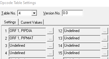
To use these these tags with ACM in an OPC client use the USER_OPCODE.DATA_mm:n tag.
The mm defines the point within the table, the n represents the table number which are zero-based; i.e. Table No. 3 in ROCLink will be referenced by the number 2 in the OPC item.
For example, to reference the first tag in the image above use:
USER_OPCODE.DATA_01:3 (first point, fourth table)
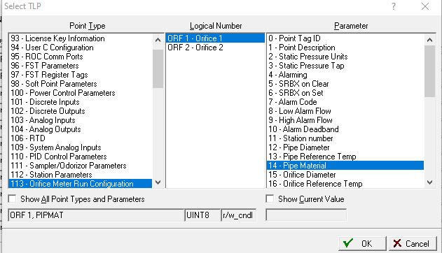
Polling USER_OPCODE.DATA_01:3 will return the TLP of the tag, not the value. To poll the value you must apply the <T***> modifier such as:
USER_OPCODE.DATA_01:3<TFLP> for floating point or:
USER_OPCODE.DATA_01:3<TINT8> for an 8-bit integer. See the Data Types section above for a complete list of <T***> modifiers.
How do I know if my tag is floating point or integer? When you define the tag in ROCLink by clicking the ellipsis button next to the tag, you see the data type on that dialog (in this case UINT8):
| Item | Data Type | Description | T.P:L |
|---|---|---|---|
USER_OPCODE.DATA_mm:n | STRING | Parameter of the configurable Opcode point where mm is a two digit decimal number from 01 to 44 and n represents the table (zero-based). | 0.m:n |
USER_OPCODE.REVISION:n | R4 | Sequence/Revision number of the configurable Opcode point where the n is the logical number. | 0.0:n |
Point Type 1 - Discrete Input Items
| Item | Data Type | Description | T.P:L |
|---|---|---|---|
DI.POINT_TAG_ID:n | STRING | 10 character name for the discrete input. | 1.0:n |
DI.FILTER:n | UI1 | Number of time intervals required in high state for input to be considered high. Bit 2 of the mode parameter is used to determine the time basis. | 1.1:n |
DI.STATUS:n | UI1 | The state of the input. Normally, a value of 1 is high and a value of 0 is low. This can be reversed by setting bit 7 of the mode parameter (Invert Enable). | 1.2:n |
DI.MODE:n | UI1 | Bitmask settings for the discrete input • Bit 0: Invert Enable (1 = Invert, 0 = Normal) • Bit 1: Latch Enable (1 = Latch on Set, 0 = Normal) • Bit 2: Filter Interval 0 = 250 msec. (50 msec. for built in DI) 1 = 15 sec (3 sec for built in DI)) • Bit 3: TDI Enable (1 = Timed Discrete Input, 0 = Normal) • Bit 4: ALM Enable (1 = Alarm checking active, 0 = No alarm checking) • Bit 5: RBX on Clear (1 = Generate RBX when exiting alarm condition, 0 = No RBX generated) • Bit 6: RBX on Set (1 = Generate RBX when entering alarm condition, 0 = No RBX generated) • Bit 7: Manual Mode (1 = scan disabled, 0 = Normal scan) | |
DI.ALARM_CODE:n | UI1 | Bitmask containing alarm information • Bit 0: TDI Low Alarm • Bit 1: TDI Low Low Alarm • Bit 2: TDI High Alarm • Bit 3: TDI High High Alarm • Bit 4: TDI Rate Alarm • Bit 5: Status Change • Bit 6: Not used • Bit 7: Manual mode READ ONLY. | 1.4:n |
DI.ACCUM_VALUE:n | UI4 | Number of 0 to 1 transitions. | 1.5:n |
DI.ON_COUNTER:n | UI4 | Number of scan periods when the Status parameter is in the 1 state. | 1.6:n |
DI.OFF_COUNTER:n | UI4 | Number of scan periods when the Status parameter is in the 0 state. | 1.7:n |
DI.0_COUNT:n | I2 | Number of scan periods that represent a 0 percent input pulse width (TDI). | 1.8:n |
DI.100_COUNT:n | I2 | Number of scan periods that represent a 100 percent input pulse width (TDI). | 1.9:n |
DI.MAX_COUNT:n | UI2 | The number of scan periods in which the input must make a transition from the 0 to 1 state (TDI). | 1.10:n |
DI.UNITS:n | STRING | 10 character name for the engineering units (TDI). | 1.11:n |
DI.SCAN_PERIOD:n | UI2 | The number of scan periods between Status updates. | 1.12:n |
DI.ZERO_EU:n | R4 | EU value corresponding to 0 percent input (TDI). | 1.13:n |
DI.SPAN_EU:n | R4 | EU value corresponding to 100 percent input (TDI). | 1.14:n |
DI.LOW_ALARM:n | R4 | EU value representing the low alarm threshold (TDI). | 1.15:n |
DI.HIGH_ALARM:n | R4 | EU value representing the high alarm threshold (TDI). | 1.16:n |
DI.LOLO_ALARM:n | R4 | EU value representing the low low alarm threshold (TDI). | 1.17:n |
DI.HIHI_ALARM:n | R4 | EU value representing the high high alarm threshold (TDI). | 1.18:n |
DI.DELTA_ALARM:n | R4 | EU value representing greatest allowable change between scans before generating an alarm (TDI). | 1.19:n |
DI.ALARM_DEADBAND:n | R4 | EU value representing a dead zone above high alarm limits and below the low alarm limits to prevent spurious alarms (TDI). | 1.20:n |
DI.EU_VALUE:n | R4 | Calculated EU value (TDI). | 1.21:n |
DI.TDI_COUNT:n | UI2 | The number of scan periods that the pulse width of the input signal is in the 1 state (TDI). READ ONLY. | 1.22:n |
Point Type 2 - Discrete Output Items
| Item | Data Type | Description | T.P:L |
|---|---|---|---|
DO.POINT_TAG_ID:n | STRING | 10 character name for the discrete output. | 2.0:n |
DO.TIME_ON:n | UI2 | Number of 50 msec. intervals the output is on. | 2.1:n |
DO.SPARE_1:n | UI1 | Parameter number 2. Not Used. READ ONLY. | 2.2:n |
DO.STATUS:n | UI1 | The current state of the output. | 2.3:n |
DO.MODE:n | UI1 | Bitmask settings for the discrete output. • Bit 0: Momentary (0 = Disable, 1 = Enable) • Bit 1: Toggle (0 = Disable, 1 = Enable) • Bit 2: Not Used (Do not set) • Bit 3: TDO Enable (1 = Timed Discrete Output, 0 = Normal) • Bit 4: CLR on Reset (0 = Disable, 1 =Enable) • Bit 5: Not Used • Bit 6: Not Used • Bit 7: Manual Mode (1 = scan disabled, 0 = Normal scan) | 2.4:n |
DO.ALARM_CODE:n | UI1 | Bitmask settings for the discrete output. • Bit 0-5: Not Used • Bit 6: Point Fail (FloBoss 107 Only) • Bit 7: Manual Mode | 2.5:n |
DO.ACCUM_VALUE:n | UI4 | Number of 0 to 1 transitions. | 2.6:n |
DO.UNITS:n | STRING | 10 character name for the Engineering Units. | 2.7:n |
DO.CYCLE_TIME:n | UI2 | The sum of the on and off time (1 cycle time) in 50 msec. periods. | 2.8:n |
DO.0_COUNT:n | I2 | The count in 50 msec. periods that represent a 0 percent output pulse width. | 2.9:n |
DO.100_COUNT:n | I2 | The count in 50 msec. periods that represent a 100 percent output pulse width. | 2.10:n |
DO.LOW_READING_EU:n | R4 | The EU value corresponding to the 0 percent count. | 2.11:n |
DO.HIGH_READING_EU:n | R4 | The EU value corresponding to the 100 percent count. | 2.12:n |
DO.EU_VALUE:n | R4 | EU value that corresponds to the amount of on-time for the discrete output. | 2.13:n |
| DO.ALARM_MODE:n | UI1 | Indicates the alarm mode.
Note: Valid only for the FB107. | 2.14:n |
| DO.SCAN_MODE:n | UI1 | Indicates scanning mode. Valid values are 0 (Automatic) and 1 (Manual). Note: Valid only for the FB107. | 2.15:n |
| DO.MANUAL_STATE:n | UI8 | Manual state (FB107 only). | 2.16:n |
| DO.PHYSICAL_STATE:n | UI8 | Physical state (FB107 only). | 2.17:n |
Point Type 3 - Analog Input Items
| Item | Data Type | Description | T.P:L |
|---|---|---|---|
AI.POINT_TAG_ID:n | STRING | 10 character name for the analog input. | 3.0:n |
AI.UNITS:n | STRING | 10 character name for the Engineering Units. | 3.1:n |
AI.SCAN_PERIOD:n | UI2 | Time between updates in 50 msec. intervals. | 3.2:n |
AI.FILTER:n | UI2 | Percentage of last value used in calculating current value. | 3.3:n |
AI.ADJUSTED_ATOD_0:n | I2 | A/D value corresponding to 0 percent input. | 3.4:n |
AI.ADJUSTED_ATOD_100:n | I2 | A/D value corresponding to 100 percent input. | 3.5:n |
AI.LOW_READING_EU:n | R4 | EU value corresponding to 0 percent input. | 3.6:n |
AI.HIGH_READING_EU:n | R4 | EU value corresponding to 100 percent input. | 3.7:n |
AI.LOW_ALARM_EU:n | R4 | EU value representing the low alarm threshold. | 3.8:n |
AI.HIGH_ALARM_EU:n | R4 | EU value representing the high alarm threshold. | 3.9:n |
AI.LOLO_ALARM_EU:n | R4 | EU value representing the low low alarm threshold. | 3.10:n |
AI.HIHI_ALARM_EU:n | R4 | EU value representing the high high alarm threshold. | 3.11:n |
AI.DELTA_ALARM_EU:n | R4 | EU value representing greatest allowable change between scans before generating an alarm. | 3.12:n |
AI.ALARM_DEADBAND:n | R4 | EU value representing a dead zone above high alarm limits and below the low alarm limits to prevent spurious alarms. | 3.13:n |
AI.FILTERED_EU:n | R4 | The current value in engineering units. | 3.14:n |
AI.MODE:n | UI1 | Bitmask settings for the analog input. • Bit 0: Not Used • Bit 1: Low Low and High High Clamping (0 = Disable, 1 = Enable) • Bit 2: Temperature Compensation (0 = Enable, 1 = Disable) • Bit 3: Use Average Input (0 = Disable, 1 = Enable) • Bit 4: ALM Enable (0 = Disable, 1 = Enable) • Bit 5: RBX on Clear (0 = Disable, 1 = Enable) • Bit 6: RBX on Set (0 = Disable, 1 = Enable) • Bit 7: Manual Mode (0 = Disable, 1 = Enable) | 3.15:n |
AI.RAW_ATOD_INPUT:n | I2 | Raw A/D input reading: READ ONLY IN ROC 300 SERIES AND FB 407. R/W IN FB 100 SERIES AND FB 500 SERIES. | 3.17:n |
AI.ACTUAL_SCAN:n | UI2 | Actual scan time. Should be the same as Scan Period unless system is overloaded. READ ONLY. | 3.18:n |
AI.FAULT_EU_VALUE:n | R4 | Fault EU Value | 3.19:n |
AI. CALIB_ZERO_RAW:n | UI2 | Calibrated Zero Raw | 3.20:n |
AI.CALIB_MID_RAW_1:n | UI2 | Calibrated Mid-point Raw #1 A/D Value | 3.21:n |
AI.CALIB_MID_RAW_2:n | UI2 | Calibrated Mid-point Raw #2 A/D Value | 3.22:n |
AI.CALIB_MID_RAW_3:n | UI2 | Calibrated Mid-point Raw #3 A/D Value | 3.23:n |
AI.CALIB_SPAN_RAW:n | UI2 | Calibrated Span Raw | 3.24:n |
AI.CALIB_ZERO_EU_VALUE:n | R4 | Calibrated Zero EU Value | 3.25:n |
AI.CALIB_MID_EU_VALUE_1:n | R4 | Calibrated Mid-point EU #1 | 3.26:n |
AI.CALIB_MID_EU_VALUE_2:n | R4 | Calibrated Mid-point EU #2 | 3.27:n |
AI.CALIB_MID_EU_VALUE_3:n | R4 | Calibrated Mid-point EU #3 | 3.28:n |
AI.CALIB_SPAN_EU:n | R4 | Calibrated Span EU | 3.29:n |
AI.OFFSET_ADDED_CALC_EU:n | R4 | Offset to be added to all calculated EU fields | 3.30:n |
AI_CALIB_SET_VALUE_ED:n | R4 | Calibrated set value; desired ED value for a calibrated point | 3.31:n |
AI_CALIB_MANUAL_VALUE:n | R4 | Calibrated manual value; the current EU value of the AI while performing calibration | 3.32:n |
AI.CALIB_TIMER:n | UI2 | Calibration Timer-number of seconds until a timeout occurs | 3.33:n |
AI.CALIB_TIMER:n | UI2 | Calibration Timer-number of seconds until a timeout occurs | 3.33:n |
AI.CALIB_MODE:n | UI8 | Calibration Mode • 0 = Use current calibration • 1 = Start calibration • 2 = Calibrate input • 3 = Restore previous calibration values • 4 = End calibration Note: No event is logged for this parameter | 3.34:n |
AI.CALIB_TYPE:n | UI8 | Calibration Mode
| 3.35:n |
t
Point Type 4 - Analog Output Items
| Item | Data Type | Description | T.P:L |
|---|---|---|---|
AO.POINT_TAG_ID:n | STRING | 10 character name for the analog output. | 4.0:n |
AO.UNITS:n | STRING | 10 character name for the Engineering Units. | 4.1:n |
AI.ADJUSTED_ATOD_0:n | I2 | A/D value corresponding to 0 percent output. | 4.2:n |
AO.ADJUSTED_ATOD_100:n | I2 | A/D value corresponding to 100 percent output. | 4.3:n |
AO.LOW_READING_EU:n | R4 | EU value corresponding to 0 percent output. | 4.4:n |
AO.HIGH_READING_EU:n | R4 | EU value corresponding to 100 percent output. | 4.5:n |
AO.VALUE_EU:n | R4 | EU value represents the last analog output scan. | 4.6:n |
AO.MODE:n | UI1 | Bitmask settings for the analog output • Bit 0: Not Used • Bit 1: Not Used • Bit 2: Not Used • Bit 3: Clear on Reset (0 = Disable, 1 = Enable) • Bit 4: ALM Enable (0 = Disable, 1 = Enable) • Bit 5: RBX on Clear (0 = Disable, 1 = Enable) • Bit 6: RBX on Set (0 = Disable, 1 = Enable) • Bit 7: Manual Mode (0 = Disable, 1 = Enable) | 4.7:n |
AO.ALARM_CODE:n | UI1 | Bitmask alarm codes • Bit 0: Not Used • Bit 1: Not Used • Bit 2: Not Used • Bit 3: Not Used • Bit 4: Not Used • Bit 5: Not Used • Bit 6: Point Fail • Bit 7: Manual Mode READ ONLY. | 4.8:n |
AO.RAW_ATOD_INPUT:n | I2 | Raw A/D input reading. READ ONLY. | 4.9:n |
AO.SCAN_MODE:n | UI1 | Scan mode-valid values are 0 (Automatic) and 1 (Manual) | 4.10:n |
AO_MANUAL_EU:n | R4 | Indicates the Manual EU | 4.11:n |
AO.PHYSICAL_EU:n | R4 | Indicates the Physical EU | 4.12:n |
Point Type 5 - Pulse Input Items
| Item | Data Type | Description | T.P:L |
|---|---|---|---|
PULSE.POINT_TAG_ID:n | STRING | 10 character name for the pulse input. | 5.0:n |
PULSE.UNITS:n | STRING | 10 character name for the Engineering Units. | 5.1:n |
PULSE.RATE_FLAG:n | UI1 | Type of pulse input selected • 0: Rate mode • 1: Accumulator, maximum Rollover • 2: Accumulator, entered Rollover | 5.2:n |
PULSE.RATE_PERIOD:n | UI1 | Time period used for rate calculation • 0: EU/minute • 1: EU/hour • 2: EU/day | 5.3:n |
PULSE.TYPE:n | UI1 | Type of measurement performed. READ ONLY. | 5.4:n |
PULSE.SCAN_PERIOD:n | UI2 | 50 msec. intervals between scans of the EU value. | 5.5:n |
PULSE.CONVERSION:n | R4 | The number of pulses times this number equals the Units. | 5.6:n |
PULSE.LOW_ALARM_EU:n | R4 | EU value representing the low alarm threshold. | 5.7:n |
PULSE.HIGH_ALARM_EU:n | R4 | EU value representing the high alarm threshold. | 5.8:n |
PULSE.LOLO_ALARM_EU:n | R4 | EU value representing the low low alarm threshold. | 5.9:n |
PULSE.HIHI_ALARM_EU:n | R4 | EU value representing the high high alarm threshold. | 5.10:n |
PULSE.DELTA_ALARM_EU:n | R4 | EU value representing greatest allowable change between scans before generating an alarm. | 5.11:n |
PULSE.ALARM_DEADBAND:n | R4 | The dead zone for alarms or the rollover value depending on the Rate Flag. | 5.12:n |
PULSE.VALUE_EU:n | R4 | The measured value, either EUs per unit of time or accumulated EUs, depending on the Rate Period. | 5.13:n |
PULSE.MODE:n | UI1 | Bitmask settings for the Pulse Input • Bit 0: Not Used • Bit 1: Not Used • Bit 2: Not Used • Bit 3: Conversion (1 = Direct, 0 = Reciprocal) • Bit 4: ALM Enable (1 = Enable, 0 = Disable) • Bit 5: RBX on Clear (1 = Enable, 0 = Disable) • Bit 6: RBX on Set (1 = Enable, 0 = Disable) • Bit 7: Manual Mode (1 = Manual, 0 = Normal) | 5.14:n |
PULSE.ALARM_CODE:n | UI1 | Bitmask alarm codes • Bit 0: Low Alarm • Bit 1: Low Low Alarm • Bit 2: High Alarm • Bit 3: High High Alarm • Bit 4: Rate Alarm • Bit 5: Not Used • Bit 6: Not Used • Bit 7: Manual Mode READ ONLY. | 5.15:n |
PULSE.ACCUM_VALUE:n | UI4 | The value of raw counts accumulated during each scan period. READ ONLY FOR INDUSTRY CANADA UNITS. | 5.16:n |
PULSE.CURRENT_RATE:n | R4 | EU value representing the rate as of the most recent scan. READ ONLY. | 5.17:n |
PULSE.TOTAL_TODAY:n | R4 | Total EUs accumulated since the most recent contract hour. | 5.18:n |
PULSE.TOTAL_YD:n | R4 | Total EUs accumulated during the most recent 24 hours since the last contract hour. READ ONLY. | 5.19:n |
PULSE.CONT_ACCUM:n | UI4 | Continuous Accumulator. READ ONLY NOTE: This item is supported in Industry Canada ROC devices only and replaces the PULSE.TOTAL_YD item. Enable the Industry Canada ROC type in the device screen. | 5.19:n |
PULSE.PULSE_FOR_DAY:n | UI4 | Pulses for Day. NOTE: This item is supported in FB 500 series devises only. | 5.20:n |
PULSE.FREQ:n | R4 | Frequency in Hertz | 5.21:n |
Point Type 5 – Pulse Input Items (Alternates)
| Item | Data Type | Description | T.P:L |
|---|---|---|---|
PULSE.CONT_ACCUM:n | UI32 | Continuous accumulator (for Industry Canada) | 5.19:n |
Point Type 6 - PID Items
| Item | Data Type | Description | T.P:L |
|---|---|---|---|
PID.POINT_TAG_ID:n | STRING | 10 character name for the PID. | 6.0:n |
PID.CONTROL_TYPE:n | UI1 | Bitmask settings for control • Bit 0: Operation Mode (0 = Manual, 1 = Automatic) • Bit 1: Control Type (0 = Primary, 1 = Override) • Bit 2: DO Control (0 = On, 1 = Off) • Bit 3: Not Used • Bit 4: PID shutdown on ROC restart (0 = Disable, 1 = Enable) • Bit 5: Not Used • Bit 6: Manual Tracking Enable (0 = Disable, 1 = Enable) • Bit 7: PID Loop Shutdown Bit (0 = Shutdown, 1 = Operational) | 6.1:n |
PID.LOOP_STATUS:n | UI1 | Current state of PID algorithm. • 0 = Primary and Override loops disabled • 1 = Primary loop running • 2 = Override loop running READ ONLY. | 6.2:0 |
PID.ACTUAL_SCAN_TIME:n | UI2 | Number of 50 msec. periods between PID scans. READ ONLY. | 6.3:n |
PID.PRI_INPUT_VAR:n | STRING | Primary input point. | 6.4:n |
PID.PRI_OUTPUT_VAR:n | STRING | Primary output point. | 6.5:n |
PID.PRI_SW_SETPOINT:n | R4 | Input value at which control passes to override control loop. | 6.6:n |
PID.PRI_SW_VAR:n | STRING | Primary switch process variable | 6.7:n |
PID.PRI_SW_MODE:n | STRING | Comparison type (greater than, less than) that causes switch-over from primary to override control loop. | 6.8:n |
PID.OVR_INPUT_VAR:n | STRING | Override input point. | 6.9:n |
PID.OVR_OUTPUT_VAR:n | STRING | Override output point – second output of PID. | 6.10:n |
PID.OVR_SW_SETPOINT:n | R4 | Input value at which control passes to primary control loop. | 6.11:n |
PID.OVR_SW_VAR:n | STRING | Override switch process variable | 6.12:n |
PID.OVR_SW_MODE:n | STRING | Comparison type (greater than, less than) that causes switch-over from override to primary control loop. | 6.13:n |
PID.PRI_SETPOINT:n | R4 | Setpoint is used for controlling the primary process variable. | 6.14:n |
PID.PRI_CHANGE_EU_MIN:n | R4 | The maximum rate at which the primary process variable is allowed to ramp to a new set point. | 6.15:n |
PID.PRI_LOOP_PERIOD:n | UI2 | The amount of time between PID calculations in 50 msec. periods for the primary loop calculations. | 6.16:n |
PID.PRI_P_GAIN:n | R4 | Ratio of change in output to change in input based on continuous linear relationship for the primary control loop. | 6.17:n |
PID.PRI_I_GAIN:n | R4 | Ratio of change in output to change in input based on time relationship for the primary control loop. | 6.18:n |
PID.PRI_D_GAIN:n | R4 | Ratio of change in output to change in input based on rate of change relationship for the primary control loop. | 6.19:n |
PID.PRI_SCALE_FACTOR:n | R4 | Ratio of output span to input span for the primary control loop. | 6.20:n |
PID.PRI_DEADBAND:n | R4 | Dead zone around setpoint in which integral action is disabled for the primary control loop. | 6.21:n |
PID.PRI_PV:n | R4 | Current value of primary control loop process variable. | 6.22:n |
PID.PRI_OUTPUT_EU:n | R4 | EU value of output of primary PID loop. | 6.23:n |
PID.PRI_SW_PV_EU:n | R4 | Input value that is compared to the primary switch value which is used to determine if control should be passed to the override control loop. | 6.24:n |
PID.MIN_CTL_TIME:n | UI2 | The minimum amount of time (in 50 msec. periods) that the primary or override control loop must maintain control before switching back to the other control loop. | 6.25:n |
PID.OVR_SETPOINT:n | R4 | Setpoint is used for controlling the override process variable. | 6.26:n |
PID.OVR_CHANGE_EU_MIN:n | R4 | The maximum rate at which the override process variable is allowed to ramp to a new setpoint. | 6.27:n |
PID.OVR_LOOP_PERIOD:n | UI2 | The amount of time between PID calculations in 50 msec. periods for the override loop calculations. | 6.28:n |
PID.OVR_P_GAIN:n | R4 | Ratio of change in output to change in input based on continuous linear relationship for the override control loop. | 6.29:n |
PID.OVR_I_GAIN:n | R4 | Ratio of change in output to change in input based on time relationship for the override control loop. | 6.30:n |
PID.OVR_D_GAIN:n | R4 | Ratio of change in output to change in input based on rate of change relationship for the override control loop. | 6.31:n |
PID.OVR_SCALE_FACTOR:n | R4 | Ratio of output span to input span for the override control loop. | 6.32:n |
PID.OVR_DEADBAND:n | R4 | Dead zone around setpoint in which integral action is disabled for the override control loop. | 6.33:n |
PID.OVR_PV:n | R4 | Current value of override control loop process variable. | 6.34:n |
PID.OVR_OUTPUT_EU:n | R4 | EU value of output of override PID loop. | 6.35:n |
PID.OVR_SW_PV_EU:n | R4 | Input value that is compared to the override switch value which is used to determine if control should be passed to the primary control loop. | 6.36:n |
Point Type 7 - AGA Items -
| Item | Data Type | Description | T.P:L |
|---|---|---|---|
AGA.POINT_TAG_ID | STRING | 10 character name for the AGA. | 7.0:n |
AGA.LATITUDE:n | R4 | Geographic latitude of metering location. | 7.1:n |
AGA.ELEVATION:n | R4 | Elevation of metering location. | 7.2:n |
AGA.CALC_METHOD:n | UI1 | Bitmask setting for calculation method • Bit 0: Super compressibility method (0 = NX-19, 1 = AGA8) • Bit 1: Calculation method (0 = AGA3, 1 = AGA7) • Bit 2: AGA3 algorithm (0 = 1985, 1 = 1992) • Bit 3: Units (0 = US, 1 = Metric) • Bit 4: ALM Enable (0 = Disable, 1 = Log Alarms) • Bit 5: RBX on Clear (0 = Disable, 1 = Enable) • Bit 6: RBX on Set (0 = Disable, 1 = Enable) • Bit 7: Not Used | 7.3:n |
AGA.OPTIONS:n | UI1 | Bitmask configuration options • Bit 0: Tap type (0 = Flange, 1 = Pipe) • Bit 1: Specific Gravity (0 = Calculate, 1 = Entered) • Bit 2: Static Pressure (0 = Downstream, 1 = Upstream) • Bit 3: Static Pressure (0 = Gauge, 1 = Absolute) • Bit 4: Heating Value (0 = Calculate, 1 = Entered) • Bit 5: Acceleration (0 = Calculate, 1 = Entered) • Bit 6: Heating Value (0 = Mass, 1 = Volume) • Bit 7: Not Used | 7.4:n |
AGA.SPECIFIC_GRAVITY:n | R4 | Specific gravity. | 7.5:n |
AGA.HEATING_VALUE:n | R4 | Heating value. | 7.6:n |
AGA.GRAV_ACCEL_ CORRECTION:n | R4 | Gravitational Acceleration value. | 7.7:n |
AGA.SCAN_PERIOD:n | UI2 | Number of 50 msec. periods between flow calculations. Note: This item does not exist in the NEW_AGA section of item tags. | 7.8:n |
AGA.PIPE_DIAMETER:n | R4 | Inside pipe diameter used for AGA3 calculation. | 7.9:n |
AGA.ORIFICE_DIAMETER:n | R4 | Orifice diameter used for AGA3 calculation. | 7.10:n |
AGA.ORIFICE_MEASURED_TE MP:n | R4 | Orifice plate temperature. | 7.11:n |
AGA.ORIFICE_MATERIAL:n | UI1 | Orifice plate material (0 = Stainless steel, 1 = Monel, 2 = Carbon Steel) | 7.12:n |
AGA.DESCRIPTION:n | STRING | 30 character description of meter run. | 7.13:n |
AGA.ALARM_CODE:n | UI1 | Bitmask alarm fields
| 7.14:n |
AGA.LOW_ALARM_EU:n | R4 | Flow value that triggers a low alarm. | 7.15:n |
AGA.HIGH_ALARM_EU:n | R4 | EU value representing the high alarm threshold. | 7.16:n |
AGA.VISCOSITY:n | R4 | Viscosity of flowing gas. | 7.17:n |
AGA.SPECIFIC_HEAT_RATIO:n | R4 | Specific Heat Ratio. | 7.18:n |
AGA.CONTRACT_PRESSURE:n | R4 | Flow measurement pressure specified in gas contract. | 7.19:n |
AGA.CONTRACT_TEMP:n | R4 | Flow measurement temperature specified in gas contract. | 7.20:n |
AGA.DP_LOW_CUTOFF:n | R4 | Low flow limits that sets flow calculation to zero. ORIFICE | 7.21:n |
AGA.KFACTOR | R4 | Low flow limits that sets flow calculation to zero. TURBINE FB 504, 104, AND 107 ONLY. | 7.21:n |
AGA.MFACTOR | R4 | Low flow limits that sets flow calculation to zero. TURBINE FB 407 VERSION 1.10 OR GREATER ONLY. | 7.21:n |
AGA.GRAVITY_CORRECTION:n | R4 | Correction for local gravity. | 7.22:n |
AGA.NITROGEN:n | R4 | Mole percent Nitrogen. | 7.23:n |
AGA.CARBON_DIOXIDE:n | R4 | Mole percent Carbon Dioxide. | 7.24:n |
AGA.HYDROGEN_SULFIDE:n | R4 | Mole percent Hydrogen Sulfide. | 7.25:n |
AGA.WATER:n | R4 | Mole percent Water. | 7.26:n |
AGA.HELIUM:n | R4 | Mole percent Helium. | 7.27:n |
AGA.METHANE:n | R4 | Mole percent Methane. | 7.28:n |
AGA.ETHANE:n | R4 | Mole percent Ethane. | 7.29:n |
AGA.PROPANE:n | R4 | Mole percent Propane. | 7.30:n |
AGA.N_BUTANE:n | R4 | Mole percent n-Butane. | 7.31:n |
AGA.I_BUTANE:n | R4 | Mole percent i-Butane. | 7.32:n |
AGA.N_PENTANE:n | R4 | Mole percent n-Pentane. | 7.33:n |
AGA.I_PENTANE:n | R4 | Mole percent i-Pentane. | 7.34:n |
AGA.N_HEXANE:n | R4 | Mole percent n-Hexane. | 7.35:n |
AGA.N_HEPTANE:n | R4 | Mole percent n-Heptane. | 7.36:n |
AGA.N_OCTANE:n | R4 | Mole percent n-Octane. | 7.37:n |
AGA.N_NONANE:n | R4 | Mole percent n-Nonane. | 7.38:n |
AGA.N_DECANE:n | R4 | Mole percent n-Decane. | 7.39:n |
AGA.OXYGEN:n | R4 | Mole percent Oxygen. | 7.40:n |
AGA.CARBON_MONOXIDE:n | R4 | Mole percent Carbon Monoxide. | 7.41:n |
AGA. HYDROGEN:n | R4 | Mole percent Hydrogen. | 7.42:n |
AGA.SPARE_1:n | UI1 | Not used. | 7.43:n |
AGA.ENABLE_STACK_UP:n | UI1 | Using stacked differential pressure transmitters. | 7.44:n |
AGA.LOW_DP_VAR:n | STRING | Low differential pressure (hw) input. | 7.45:n |
AGA.DP_VAR:n | STRING | Differential Pressure (hw) Input. ORIFICE | 7.46:n |
AGA.FLOW_RATE_INPUT | STRING | Flow Rate Input TURBINE | 7.46:n |
AGA.PF_VAR:n | STRING | Static pressure input – Pf. | 7.47:n |
AGA.TF_VAR:n | STRING | Temperature input – Pf. | 7.48:n |
AGA.LOW_DP_SETPOINT:n | R4 | Setpoint value at which switchover to low differential pressure input occurs. | 7.49:n |
AGA.HIGH_DP_SETPOINT:n | R4 | Setpoint value at which switchover to high differential pressure input occurs. | 7.50:n |
AGA.HW:n | R4 | Differential pressure. | 7.51:n |
AGA.PF:n | R4 | Static pressure. | 7.52:n |
AGA.TF:n | R4 | Temperature of flowing fluid. | 7.53:n |
Point Type 7 – AGA (Alternate)
| Item | Data Type | Description | T.P:L |
|---|---|---|---|
AGA.KFACTOR:n | R4 | k-Factor (107, 504, 104) | 7.21:n |
AGA.MFACTOR:n | R4 | k-Factor (407 turbine version 1.1 or greater)) | 7.21:n |
AGA.FLOW_RATE_INPUT:n | R4 | k-Factor (turbine) | 7.46:n |
Point Type 8 – HISTORY Items
| Item | Data Type | Description | T.P:L |
|---|---|---|---|
HISTORY.POINT_TAG_ID_mm:n | STRING | Where mm is a two digit decimal number from 01 to 15 | 8.P:n |
HISTORY.POINT_mm:n | STRING | Where mm is a two digit decimal number from 01 to 15 | 8.P:n |
HISTORY.ARCHIVE_TYPE_mm:n | UI1 | Where mm is a two digit decimal number from 01 to 15 | 8.P:n |
HISTORY.RATE_TYPE_mm:n | UI1 | Where mm is a two digit decimal number from 01 to 15 | 8.P:n |
Point Type 9 - LCD Items
| Item | Data Type | Description | T.P:L |
|---|---|---|---|
LCD.TEXT_LINE1:n | STRING | Text for display line 1. | 9.0:n |
LCD.TEXT_LINE2:n | STRING | Text for display line 2. | 9.1:n |
LCD.TEXT_LINE3:n | STRING | Text for display line 3. | 9.2:n |
LCD.DATA_LINE1_VAR:n | STRING | Data for line 1. | 9.3:n |
LCD.DATA_LINE2_VAR:n | STRING | Data for line 2. | 9.4:n |
LCD.DATA_LINE3_VAR:n | STRING | Data for line 3. | 9.5:n |
Point Type 10 - AGA Flow Items -
| Item | Data Type | Description | T.P:L |
|---|---|---|---|
AGAFLOW.DP:n or AGAFLOW.HW:n | R4 | Differential pressure. ORIFICE READ ONLY. | 10.0:n |
AGAFLOW.UNCORRECTED_FLOW:n | R4 | Uncorrected Flow. TURBINE READ ONLY. | 10.0:n |
AGAFLOW.PF:n | R4 | Static pressure. READ ONLY. | 10.1:n |
AGAFLOW.TF:n | R4 | Temperature of flowing fluid. READ ONLY. | 10.2:n |
AGAFLOW.MCF_PER_DAY:n | R4 | Instantaneous flow rate in thousands of cubic feet per day. READ ONLY. | 10.3:n |
AGAFLOW.MMBTU_PER_DAY:n | R4 | Instantaneous energy rate in millions of cubic feet per day. READ ONLY. | 10.4:n |
AGAFLOW.MCF_TODAY:n | R4 | Accumulated flow rate since start of contract day in thousands of cubic feet. READ ONLY IN FB 500 - SERIES. | 10.5:n |
AGAFLOW.MMBTU_TODAY:n | R4 | Accumulated energy rate since start of contract day in millions of cubic feet. READ ONLY IN FB 500 – SERIES. | 10.6:n |
AGAFLOW.MCF_YD:n | R4 | Accumulated flow rate in thousands of cubic feet in 24 hour period prior to start of current Contract day. READ ONLY IN FB 500 – SERIES. | 10.7:n |
AGAFLOW.MCF_CONT_ACCUM:n | UI4 | Flow continuous accumulated. NOTE: THIS ITEM IS SUPPORTED IN INDUSTRY CANADA ROC DEVICES ONLY AND REPLACES THE AGAFLOW. MCF_YD ITEM. ENABLE THE INDUSTRY CANADA ROC TYPE IN THE DEVICE SCREEN. | 10.7:n |
AGAFLOW.MMBTU_YD:n | R4 | Accumulated energy rate in millions of cubic feet in 24 hour period prior to start of current Contract day. READ ONLY IN FB 500 - SERIES. | 10.8:n |
AGAFLOW.MMBTU_CONT_ACCUM:n | UI4 | Energy continuous accumulated. NOTE: THIS ITEM IS SUPPORTED IN INDUSTRY CANADA ROC DEVICES ONLY AND REPLACES THE AGAFLOW. MMBTU_YD ITEM. ENABLE THE INDUSTRY CANADA ROC TYPE IN THE DEVICE SCREEN. | 10.8:n |
AGAFLOW.PRESSURE_EXT:n | R4 | Calculated pressure extension value. READ ONLY. | 10.9:n |
AGAFLOW.C_PRIME:n | R4 | Calculated C' value. READ ONLY. | 10.10:n |
AGAFLOW.SAMPLE_TIME:n | R4 | Sample time value. READ ONLY. Note: This item does not exist in the NEW_AGAFLOW section of item tags. | 10.11:n |
AGAFLOW.EXPANSION_FACTOR:n | R4 | READ ONLY. | 10.12:n |
AGAFLOW.FR:n | R4 | Reynolds number value. READ ONLY. | 10.13:n |
AGAFLOW.FTF:n | R4 | Flowing temperature factor value. READ ONLY. | 10.14:n |
AGAFLOW.FPV:n | R4 | Super-compressibility factor value. READ ONLY. | 10.15:n |
AGAFLOW.FGR:n | R4 | Specific gravity factor value. READ ONLY. | 10.16:n |
AGAFLOW.FB:n | R4 | Orifice flow factor value. READ ONLY. | 10.17:n |
AGAFLOW.FPB:n | R4 | Pressure base factor value. READ ONLY. | 10.18:n |
AGAFLOW.FTB:n | R4 | Temperature base factor value. READ ONLY. | 10.19:n |
AGAFLOW.FA:n | R4 | Thermal expansion factor value. READ ONLY. | 10.20:n |
AGAFLOW.FLOW_MINUTES:n | R4 | Flowing minute (ROCPAC only). READ ONLY. Note: This item does not exist in the NEW_AGA section of item tags. | 10.21:n |
Point Type 10 – AGA Flow Items (Alternates)
| Item | Data Type | Description | T.P:L |
|---|---|---|---|
AGAFLOW.HW:n | R4 | Orifice: hw – Meter Differential Pressure Value (Inches H2O or kPa) | 10.0:n |
AGAFLOW.UNCORRECTED_FLOW:n | R4 | Turbine: Uncorrected Flow Rate | 10.9:n |
AGAFLOW.MCF_CONT_ACCUM:n | R4 | Flow Continuous Accum – MCF or km3 (Industry Canada) | 10.7:n |
AGAFLOW.MMBTU_CONT_ACCUM:n | R4 | Energy Continuous Accum – MMBTU or GJ (Industry Canada) | 10.8:n |
Point Type 11 - Tank Items
| Item | Data Type | Description | T.P:L |
|---|---|---|---|
TANK.TAG:n | STRING | 10 character name for tank. | 11.0:n |
TANK.UNITS:n | STRING | 10 character name for the engineering units. | 11.1:n |
TANK.LEVEL_VAR:n | STRING | Tank level input. | 11.2:n |
TANK.METER_OUTPUT_VAR:n | STRING | Meter output (Pulse input). | 11.3:n |
TANK.SCAN_PERIOD:n | UI2 | Number of 50msec periods between volume calculations. | 11.4:n |
TANK.ALARM_CODE:n | UI1 | Bitmask of alarms • Bit 4: Rate Alarm • Others: Not Used READ ONLY. | 11.5:n |
TANK.SPARE_1:n | UI1 | Not Used. READ ONLY. | 11.6:n |
TANK.DELTA_ALARM_EU:n | R4 | The maximum drop in level between scans before an alarm is generated. | 11.7:n |
TANK.STRAPPING_VALUE:n | R4 | Factor for equating 1 inch of water column to the volumetric quantity of the tank. | 11.8:n |
TANK.SPECIFIC_GRAVITY:n | R4 | Specific gravity of the liquid stored in the tank. | 11.9:n |
TANK.LEVEL_DEADBAND:n | R4 | The amount of change in level required before the rate alarm clears. | 11.10:n |
TANK.MANUAL_ENTRY_BBLS:n | R4 | Amount of liquid manually removed from tank. | 11.11:n |
TANK.TOTAL_BBLS_HAULED:n | R4 | Sum of manually removed units. READ ONLY. | 11.12:n |
TANK.CUR_FLUID_LEVEL:n | R4 | Current liquid level in tank. READ ONLY. | 11.13:n |
TANK.MIDNIGHT_LEVEL:n | R4 | Liquid level at start of contract day. READ ONLY. | 11.14:n |
TANK.BBLS_DISCHARGED:n | R4 | Volume of liquid discharged through the turbine since start of contract day. READ ONLY. | 11.15:n |
TANK.TODAYS_VOLUME:n | R4 | Net volume gain or loss since start of contract day. READ ONLY. | 11.16:n |
TANK.YD_VOLUME:n | R4 | Yesterday's net volume gain or loss. READ ONLY. | 11.17:n |
TANK.LAST_SCAN_LEVEL:n | R4 | Level of liquid in tank at time of last scan. READ ONLY. | 11.18:n |
TANK.CORRECTED_BASE_PI:n | R4 | Corrected base PI.. READ ONLY. | 11.19:n |
Point Type 11 – Tank Items (Alternates)
| Item | Data Type | Description | T.P:L |
|---|---|---|---|
AGAFLOW.POINT_TAG_ID:n | STRING | 10 character name for tank. | 11.0:n |
Point Type 12 - Clock Items
| Item | Data Type | Description | T.P:L |
|---|---|---|---|
CLOCK.SECOND | UI1 | Current second in real time clock. | 12.0:n |
CLOCK.MINUTE | UI1 | Current minute in real time clock. | 12.1:n |
CLOCK.HOUR | UI1 | Current hour in real time clock. | 12.2:n |
CLOCK.DAY | UI1 | Current day in real time clock. | 12.3:n |
CLOCK.MONTH | UI1 | Current month in real time clock. | 12.4:n |
CLOCK.YEAR | UI1 | Current year in real time clock. 2 digit year. | 12.5:n |
CLOCK.LEAP_YEAR | UI1 | For ROC 300 series and FB 407, the number of years ago that the last leap year occurred. Equals 0 on a leap year. For FB 500 series, 1 for a leap year, 2 for not a leap year. READ ONLY IN FB 500 - SERIES. | 12.6:n |
CLOCK.DAY_OF_WEEK | UI1 | Current day of week ( 1=Sunday, 7=Saturday ). READ ONLY IN FB 500 - SERIES. | 12.7:n |
CLOCK.DATE_TIME | STRING | Date and Time string from ROC real time clock setting. The format is WWW Mmm dd,yyyy hh:mm:ss, were WWW is the Day Of The Week Text, Mmm is the Month Text, dd is the Day of the month, yyyy is the Four Digit Year, hh is the Hour, mm is the Minutes, ss is the Seconds. Example: WED Jul 11, 2001 16:34:15. All the values are read from opcode 7. READ ONLY. | 12.8:n |
CLOCK.DATE_TIME_2 | STRING | Date and Time string from ROC real time clock setting. The format is yyyy/mm/dd hh:mm:ss, where yyyy is the Four digit year, mm is the two digit month, dd is the two digit day of the month, hh is the Hour, mm is the Minutes, ss is the Seconds. All the values are read from Point type 12, Parameter number 8 using opcode 180 and 181. NOTE: This item is available in Version 5.0.1.3 and above. | 12.8:n |
CLOCK.CENTURY | UI1 | First two digits of a four digit year. NOTE: This item is supported in Industry Canada ROC devices only. Enable the Industry Canada ROC type in the device screen. | 12.9:n |
CLOCK.DAYLIGHT_SAVINGS | UI1 | • 1 for daylight savings enabled • 0 for daylight savings not enabled NOTE: This item is supported in Industry Canada ROC devices only. Enable the Industry Canada ROC type in the device SCREEN. | 12.10:n |
CLOCK.DATE | UI4 | Date from the ROC real time clock setting in the form YYYYMMDD. READ ONLY. | N/A |
CLOCK.TIME | UI4 | Time from the ROC real time clock setting in the form HHMMSS. READ ONLY. | N/A |
Point Type 12 – Clock Items (Alternates)
| Item | Data Type | Description | T.P:L |
|---|---|---|---|
CLOCK.FLAG_23:n | UI1 | Comm Port 2 Security | 12.23:n |
CLOCK.FLAG_24:n | UI1 | Manages LCD Port Security for FloBoss 107. Valid values are: 0 = Disabled 1 = Enabled; managed by password 2 = Enabled; managed by passwoprd and access level security | 12.24:n |
CLOCK.FLAG_25:n | UI1 | Sets Comm Port Pass-Through mode for FloBoss 100-Series,: 0 = No Pass Through. 1 = LOI to COM1 (103/104 and 107) 2 = COM1 to LOI (103/104), LOI to COM2 (107) 3 = LOI to COM2 (103/104), LOI to COM3 (107) 4 = COM2 to LOI (103/104), COM1 to LOI (107) 5 = COM1 to COM2 (103/104), COM1 to COM2 (107) 6 = COM2 to COM1 (103/104), COM1 to COM3 (107) 7 = COM2 to LOI (107) 8 = COM2 to COM1 (107) 9 = COM2 to COM 3 (107) 10 = COM3 to LOI (107) 11 = COM3 to COM1 (107) 12 = COM3 to COM2 (107) | 12.25:n |
CLOCK.FLAG_26:n | UI1 | For FloBoss 103/104, manages the 6 Point I/O Setup Flag: Bit 0: 0 = AI1 1 = DI1 Bit 1: 0 = AI2 1 = DI2 Bit 2: 0 = AO 1 = DO1 Bit 4: 0 = PI1 1 = DI3 Bit 5: 0 = PI2 1 = DI4 Bits 3, 6, and 7 – Not Used | 12.26:n |
CLOCK.FLAG_27:n | UI1 | Manages Comm Port 3 Security for FloBoss 107. Valid values are: 0 = Disabled 1 = Enabled; managed by password 2 = Enabled; managed by password and access level security | 12.27:n |
CLOCK.FLAG_28:n | UI1 | Manages communications port 3 RTS for FloBoss 107 only, 0 = Disabled 1 = Enable for 30 seconds | 12.28:n |
CLOCK.FLAG_29:n | UI1 | Manages the configured number of daily history logs for FloBoss 107 only, | 12.29:n |
Point Type 13 - System Flag Items
| Item | Data Type | Description | T.P:L |
|---|---|---|---|
SYSTEM_FLAG.CRC_CHECK | UI1 | Indicates the CRC check. | 13.0:n |
SYSTEM_FLAG.FLAG_1 | UI1 | System flag 1. | 13.1:n |
SYSTEM_FLAG.FLAG_2 | UI1 | System flag 2. | 13.2:n |
SYSTEM_FLAG.FLAG_3 | UI1 | System flag 3. | 13.3:n |
SYSTEM_FLAG.FLAG_4 | UI1 | System flag 4. | 13.4:n |
SYSTEM_FLAG.FLAG_5 | UI1 | System flag 5. | 13.5:n |
SYSTEM_FLAG.FLAG_6 | UI1 | System flag 6. | 13.6:n |
SYSTEM_FLAG.FLAG_7 | UI1 | System flag 7. | 13.7:n |
SYSTEM_FLAG.RTS_ROI | UI1 | Enable RTS use on operator interface port. | 13.8:n |
SYSTEM_FLAG.RTS_COMM1 | UI1 | Enable RTS use on communications port 1. | 13.9:n |
SYSTEM_FLAG.RTS_COMM2 | UI1 | Enable RTS use on communications port 2. | 13.10:n |
SYSTEM_FLAG.CLEAR_FIRM | UI1 | Clear all saved restart data, restores factory defaults. | 13.11:n |
SYSTEM_FLAG.IO_SCAN_EN | UI1 | Enable I/O scamming. | 13.12:n |
SYSTEM_FLAG.RTS_OUT2_ON | UI1 | Control Auxiliary Output 2. | 13.13:n |
SYSTEM_FLAG. RTS_OUT1_ON | UI1 | Control Auxiliary Output 1 | 13.14:n |
SYSTEM_FLAG.COLD_START | UI1 | ROC initialized from restart configuration. | 13.15:n |
SYSTEM_FLAG.WARM_START | UI1 | ROC initialized from RAM. | 13.16:n |
SYSTEM_FLAG.READ_IO | UI1 | Forces ROC to read and update I/O configuration. | 13.17:n |
SYSTEM_FLAG.WRITE_TO_FIRM | UI1 | Save configuration settings to EEPROM. | 13.18:n |
SYSTEM_FLAG.WR_FIRM_DONE | UI1 | Signals when a write to EEPROM has completed | 13.19:n |
SYSTEM_FLAG.EVENT_LOG_FLAG | UI1 | Enables the Event Log for FB 100 Series and FB 500 Series. Enables Init. History for FB 407 and ROC 300 Series with FlashPAC | 13.20:n |
SYSTEM_FLAG.LOI_SECURITY | UI1 | Manages LOI Security | 13.21:n |
SYSTEM_FLAG.PORT_1_SECURITY | UI1 | ManagesCom Port 1Security | 13.22:n |
SYSTEM_FLAG.PORT_2_SECURITY | UI1 | ManagesCom Port 2Security | 13.23:n |
SYSTEM_FLAG.PORT_PASSTHRU_MO | Sets Comm Port Pass-Through mode: | 13.25:n | |
SYSTEM_FLAG.PT_IO_SETUP_FLAG | Manages the 6 Point I/O Setup Flag | 13.26:n | |
SYSTEM_FLAG.PORT_3_SECURITY | ManagesCom Port 3Security | 13.27:n | |
SYSTEM_FLAG.PORT_3_RTS_TEST | SetsComm Port 3 RTS Test | 13.28:n | |
SYSTEM_FLAG.CFG_DAILY_HIST | Manages the configured number of daily history logs. | 13.29:n | |
SYSTEM_FLAG.HISTORY_TS_OPT | Manages the history time stamp option. | 13.30:n | |
SYSTEM_FLAG.CFG_DAILY_HIST | Manages the configured number of daily history logs. | 13.31:n |
Point Type 13 – System Flag Items (Alternates)
| Item | Data Type | Description | T.P:L |
|---|---|---|---|
SYSTEM_FLAG.FLAG_23:n | UI1 | Comm Port 2 Security | 12.23:n |
SYSTEM_FLAG.FLAG_24:n | UI1 | Manages LCD Port Security for FloBoss 107. Valid values are: 0 = Disabled 1 = Enabled; managed by password 2 = Enabled; managed by passwoprd and access level security | 12.24:n |
SYSTEM_FLAG.FLAG_25:n | UI1 | Sets Comm Port Pass-Through mode for FloBoss 100-Series,: 0 = No Pass Through. 1 = LOI to COM1 (103/104 and 107) 2 = COM1 to LOI (103/104), LOI to COM2 (107) 3 = LOI to COM2 (103/104), LOI to COM3 (107) 4 = COM2 to LOI (103/104), COM1 to LOI (107) 5 = COM1 to COM2 (103/104), COM1 to COM2 (107) 6 = COM2 to COM1 (103/104), COM1 to COM3 (107) 7 = COM2 to LOI (107) 8 = COM2 to COM1 (107) 9 = COM2 to COM 3 (107) 10 = COM3 to LOI (107) 11 = COM3 to COM1 (107) 12 = COM3 to COM2 (107) | 12.25:n |
SYSTEM_FLAG.FLAG_26:n | UI1 | For FloBoss 103/104, manages the 6 Point I/O Setup Flag: Bit 0: 0 = AI1 1 = DI1 Bit 1: 0 = AI2 1 = DI2 Bit 2: 0 = AO 1 = DO1 Bit 4: 0 = PI1 1 = DI3 Bit 5: 0 = PI2 1 = DI4 Bits 3, 6 and 7 – Not Used | 12.26:n |
SYSTEM_FLAG.FLAG_27:n | UI1 | Manages Comm Port 3 Security for FloBoss 107. Valid values are: 0 = Disabled 1 = Enabled; managed by password 2 = Enabled; managed by passwoprd and access level security | 12.27:n |
SYSTEM_FLAG.FLAG_28:n | UI1 | Manages communications port 3 RTS for FloBoss 107 only, 0 = Disabled 1 = Enable for 30 seconds | 12.28:n |
SYSTEM_FLAG.FLAG_29:n | UI1 | Manages the configured number of daily history logs for FloBoss 107 only, | 12.29:n |
Point Type 14 - Communication Port Items
| Item | Data Type | Description | T.P:L |
|---|---|---|---|
PORT.TAG_ID:n | STRING | 10 character name for the communications port. | 14.0:n |
PORT.BAUD_RATE:n | UI2 | Transmit and receive data rate. | 14.1:n |
PORT.STOP_BITS:n | UI1 | Number of stop bits in a character. | 14.2:n |
PORT.DATA_BITS:n | UI1 | Number of data bits in a character. | 14.3:n |
PORT.PARITY:n | UI1 | Parity checks to be performed on incoming data. | 14.4:n |
PORT.STATUS:n | UI1 | Bitmask indicators of communications card status • Bit 0: No Port Installed (1 = No port installed, 0 = port installed) • Bit 1: RBX Enable (1 = RBX active, 0 = No RBX) • Bit 2: Not Used • Bit 3: Not Used • Bit 4: Not Used • Bit 5: Not Used • Bit 6: Not Used • Bit 7: User Configurable READ ONLY. | 14.5:n |
PORT.MODE:n | UI1 | Bitmask settings of communications card • Bit 0: Not Used • Bit 1: Enable RBX (0 = RBX inactive, 1 = RBX message pending) • Bit 2: Enable Extra Key-On • Bit 3: Not Used • Bit 4: Not Used • Bit 5: Not Used • Bit 6: User Configurable Flag • Bit 7: User Configurable Flag | 14.6:n |
PORT.KEY_ON_DELAY:n | UI1 | Push-to-talk delay in 50msec or 10msec intervals. | 14.7:n |
PORT.TURNAROUND_DELAY:n | UI1 | Delay between receipt of a request and the transmission of a response, in 50msec or 10msec intervals. | 14.8:n |
PORT.RETRY_COUNT:n | UI1 | Number of times a message is repeated if a valid response is not received. | 14.9:n |
PORT.RETRY_TIME:n | UI2 | Key-on delay for RBXs over trunked communications systems in 50msec or 10msec intervals. | 14.10:n |
PORT.ALARM_POINTER:n | UI2 | The pointer to the last alarm in the alarm log that triggered a RBX. READ ONLY. | 14.11:n |
PORT.RECV_COUNTER_COPY:n | UI2 | Number of received messages READ ONLY. | 14.12:n |
PORT.RETRY_COUNTER:n | UI2 | Number of retries due to no response. READ ONLY. | 14.13:n |
PORT.VALID_RECEIVE_CTR:n | UI2 | Number of valid Opcodes received on this port. | 14.14:n |
PORT.MODEM_STATUS:n | UI1 | READ ONLY. Note: This item is supported in FB 500 series, ROC 300 FlashPACs and FB 407 ver. 1.05 and greater only. | 14.15:n |
PORT.MODEM_TYPE:n | UI1 | Note: This item is supported in FB 500 series, ROC 300 FlashPACs and FB 407 ver. 1.05 and greater only. | 14.16:n |
PORT.CONNECT_TIME:n | R4 | Note: This item is supported in FB 500 series, ROC 300 FlashPACs and FB 407 ver. 1.05 and greater only. | 14.17:n |
PORT.CONFIG_COMMAND:n | STRING | Note: This item is supported in FB 500 series, ROC 300 FlashPACs and FB 407 ver. 1.05 and greater only. | 14.18:n |
PORT.CONNECT_COMMAND:n | STRING | Note: This item is supported in FB 500 series, ROC 300 FlashPACs and FB 407 ver. 1.05 and greater only. | 14.19:n |
PORT.DISCONNECT_TIME:n | R4 | Note: This item is supported in FB 500 series, ROC 300 FlashPACs and FB 407 ver. 1.05 and greater only. | 14.20:n |
PORT.INACTIVITY_TIME:n | R4 | Note: This item is supported in FB 500 series, ROC 300 FlashPACs and FB 407 ver. 1.05 and greater only. | 14.21:n |
PORT.RBX_TIME_BASE_1:n | R4 | Note: This item is supported in FB 500 series, ROC 300 FlashPACs and FB 407 ver. 1.05 and greater only. | 14.22:n |
PORT.RBX_RETRY_COUNT_1:n | UI1 | Note: This item is supported in FB 500 series, ROC 300 FlashPACs and FB 407 ver. 1.05 and greater only. | 14.23:n |
PORT.RBX_TIME_BASE_2:n | R4 | Note: This item is supported in FB 500 series, ROC 300 FlashPACs and FB 407 ver. 1.05 and greater only. | 14.24:n |
PORT.RBX_RETRY_COUNT_2:n | UI1 | Note: This item is supported in FB 500 series, ROC 300 FlashPACs and FB 407 ver. 1.05 and greater only. | 14.25:n |
PORT.RBX_TIME_BASE_3:n | R4 | Note: This item is supported in FB 500 series, ROC 300 FlashPACs and FB 407 ver. 1.05 and greater only. | 14.26:n |
PORT.RBX_RETRY_COUNT_3:n | UI1 | Note: This item is supported in FB 500 series, ROC 300 FlashPACs and FB 407 ver. 1.05 and greater only. | 14.27:n |
PORT.RBX_UNIT:n or PORT.RBX_ADDRESS:n | UI1 | Note: This item is supported in FB 500 series, ROC 300 FlashPACs and FB 407 ver. 1.05 and greater only. | 14.28:n |
PORT.RBX_GROUP:n | UI1 | Note: This item is supported in FB 500 series, ROC 300 FlashPACs and FB 407 ver. 1.05 and greater only. | 14.29:n |
PORT.STORE_FORWARD_ADDR_ 1:n | UI1 | Note: This item is supported in FB 500 series, ROC 300 FlashPACs and FB 407 ver. 1.05 and greater only. | 14.30:n |
PORT.STORE_FORWARD_GROU P_1:n | UI1 | Note: This item is supported in FB 500 series, ROC 300 FlashPACs and FB 407 ver. 1.05 and greater only. | 14.31:n |
PORT.STORE_FORWARD_ADDR_ 2:n | UI1 | Note: This item is supported in FB 500 series, ROC 300 FlashPACs and FB 407 ver. 1.05 and greater only. | 14.32:n |
PORT.STORE_FORWARD_GROU P_2:n | UI1 | Note: This item is supported in FB 500 series, ROC 300 FlashPACs and FB 407 ver. 1.05 and greater only. | 14.33:n |
PORT.STORE_FORWARD_ADDR_ 3:n | UI1 | Note: This item is supported in FB 500 series, ROC 300 FlashPACs and FB 407 ver. 1.05 and greater only. | 14.34:n |
PORT.STORE_FORWARD_GROU P_3:n | UI1 | Note: This item is supported in FB 500 series, ROC 300 FlashPACs and FB 407 ver. 1.05 and greater only. | 14.35:n |
Point Type 14 – Port Items (Alternates)
| Item | Data Type | Description | T.P:L |
|---|---|---|---|
PORT.RBX_ADDRESS:n | UI1 | RBX Address | 14.28:n |
Point Type 15 - System Items
| Item | Data Type | Description | T.P:L |
|---|---|---|---|
SYSTEM.ROC_UNIT or SYSTEM.ROC_ADDRESS | UI1 | ROC unit address for communications. | 15.0:n |
SYSTEM.ROC_GROUP | UI1 | ROC group address for communications. | 15.1:n |
SYSTEM.STATION_NAME | STRING | 20 character name or location of the ROC. | 15.2:n |
SYSTEM.ACTIVE_PIDS | UI1 | Number of PID loops that are enabled. | 15.3:n |
SYSTEM.ACTIVE_AGAS | UI1 | Number of AGA calculations that are enabled. | 15.4:n |
SYSTEM.ACTIVE_TANKS | UI1 | Number of Tank functions which are enabled. | 15.5:n |
SYSTEM.HISTORY_BASE | UI1 | Number of Base RAM history points enabled. | 15.6:n |
SYSTEM.HISTORY_1 | UI1 | Number of RAM 1 history points enabled. | 15.7:n |
SYSTEM.HISTORY_2 | UI1 | Number of RAM 2 history points enabled. | 15.8:n |
SYSTEM.HISTORY_3 | UI1 | Number of RAM 3 history points enabled. | 15.9:n |
SYSTEM.CONTRACT_HOUR | UI1 | Hour considered as start of day. | 15.10:n |
SYSTEM.PART_NUMBER | STRING | Version name. READ ONLY. | 15.11:n |
SYSTEM.FISHER_ID | STRING | Firmware identification. | 15.12:n |
SYSTEM.TIME_CREATED | STRING | Time and date when firmware was created. READ ONLY. | 15.13:n |
SYSTEM.SERIAL_NUMBER | STRING | ROM serial number. READ ONLY. | 15.14:n |
SYSTEM.CUSTOMER_NAME | STRING | Customer name for which the ROM version was created. READ ONLY. | 15.15:n |
SYSTEM.ROM_PIDS | UI1 | Maximum PID loops supported. READ ONLY. | 15.16:n |
SYSTEM.ROM_AGAS | UI1 | Maximum AGA calculations supported. READ ONLY. | 15.17:n |
SYSTEM.ROM_TANKS | UI1 | Maximum Tank functions supported. READ ONLY. | 15.18:n |
SYSTEM.FST_ACTIVE | UI1 | Number of FSTs that can be run. READ ONLY. | 15.19:n |
SYSTEM.RAM | UI1 | Number of 128K RAM segments. READ ONLY. | 15.20:n |
SYSTEM.ROM | UI1 | Number of 128K ROM segments. READ ONLY. | 15.21:n |
SYSTEM.MPU_LOADING | R4 | Percentage of time that processor is busy. READ ONLY. | 15.22:n |
SYSTEM.UTILITIES | UI1 | Bitmask utility code • Bit 0: AGA reports installed • Bit 1: LCD installed • Bit 2: COM1 User Enable • Bit 3: COM2 User Enable • Bit 4: User C Enable • Bit 5: Not Used • Bit 6: Not Used • Bit 7: Not Used READ ONLY. | 15.23:n |
SYSTEM.ROC_TYPE | UI2 | Read Only. Note: This item is supported in FB 500 series, ROC 300 FlashPACs and FB 407 ver. 1.05 and greater only. | 15.24:n |
SYSTEM.UNITS_FLAG | UI1 | Note: This item is supported in FB 500 series, ROC 300 FlashPACs and FB 407 ver. 1.05 and greater only. | 15.25:n |
SYSTEM.ENCRYPT_KEY1 | UI4 | Encryption Key 1 | 15.26:n |
SYSTEM.ENCRYPT_KEY2 | UI4 | Encryption Key 2 | 15.27:n |
SYSTEM.ENCRYPT_KEY3 | UI4 | Encryption Key 3 | 15.28:n |
SYSTEM.ENCRYPT_KEY4 | UI4 | Encryption Key 4 | 15.29:n |
SYSTEM.ENCRYPT_KEY5 | UI4 | Encryption Key 5 | 15.30:n |
SYSTEM.ENCRYPT_KEY6 | UI4 | Encryption Key 6 | 15.31:n |
SYSTEM.ENCRYPT_KEY7 | UI4 | Encryption Key 7 | 15.32:n |
SYSTEM.ENCRYPT_KEY8 | UI4 | Encryption Key 8 | 15.33:n |
Point Type 15 – System Items (Alternates)
| Item | Data Type | Description | T.P:L |
|---|---|---|---|
SYSTEM.ROC_ADDRESS:n | UI1 | ROC Address | 15.0:n |
Point Type 16 - FST Items
| Item | Data Type | Description | T.P:L |
|---|---|---|---|
FST.POINT_TAG_ID:n | STRING | 10 character name for the FST. | 16.0:n |
FST.RESULT_REG:n | R4 | The result register or SVA. | 16.1:n |
FST.REG_01:n | R4 | Register used for global storage. | 16.2:n |
FST.REG_02:n | R4 | Register used for global storage. | 16.3:n |
FST.REG_03:n | R4 | Register used for global storage. | 16.4:n |
FST.REG_04:n | R4 | Register used for global storage. | 16.5:n |
FST.REG_05:n | R4 | Register used for global storage. | 16.6:n |
FST.REG_06:n | R4 | Register used for global storage. | 16.7:n |
FST.REG_07:n | R4 | Register used for global storage. | 16.8:n |
FST.REG_08:n | R4 | Register used for global storage. | 16.9:n |
FST.REG_09:n | R4 | Register used for global storage. | 16.10:n |
FST.REG_10:n | R4 | Register used for global storage. | 16.11:n |
FST.TIMER_1:n | UI4 | Timer value. | 16.12:n |
FST.TIMER_2:n | UI4 | Timer value. | 16.13:n |
FST.TIMER_3:n | UI4 | Timer value. | 16.14:n |
FST.TIMER_4:n | UI4 | Timer value. | 16.15:n |
FST.MESSAGE_1:n | STRING | 30 character field for storing a message. | 16.16:n |
FST.MESSAGE_2:n | STRING | 30 character field for storing a message. | 16.17:n |
FST.MESSAGE_DATA:n | STRING | 10 character field for message data. READ ONLY. | 16.18:n |
FST.MISC_1:n | UI1 | Eight bits of global storage. | 16.19:n |
FST.MISC_2:n | UI1 | Eight bits of global storage. | 16.20:n |
FST.MISC_3:n | UI1 | Eight bits of global storage. | 16.21:n |
FST.MISC_4:n | UI1 | Eight bits of global storage. | 16.22:n |
FST.COMPARE_FLAG_SVD:n | UI1 | Compare value of 0 - 255. | 16.23:n |
FST.RUN_FALG:n | UI1 | Indicator of running status for FST (0 = shut down, 1 = running). | 16.24:n |
FST.CODE_SIZE:n | UI2 | Number of bytes used by the FST. NOTE: This item is supported in FB 100 series, FB 407, and ROC 300 Series only. | 16.25:n |
FST.INSTRUCTION_POINTER:n | R4 | Location in memory of next function to be executed. NOTE: This item is supported in FB 500 Series, FB 100 Series, FB 407, and ROC 300 Series only. | 16.26:n |
FST.EXECUTION_DELAY:n | UI2 | Delay in 100 msec. periods between FST commands. | 16.27:n |
FST.MSG2_DATA | STRING | Message #2 Data (for FB107): MS2 function puts its value into this parameter. | 16.28:n |
Point Type 17 - Soft Point Items
| Item | Data Type | Description | T.P:L |
|---|---|---|---|
SOFT_POINT.POINT_TAG_ID:n | STRING | 10 character name of soft point. | 17.0:n |
SOFT_POINT.INTEGER_FLAG:n | UI2 | Integer flag used by FST or User program. | 17.1:n |
SOFT_POINT.DATA_01:n | R4 | Where n represents the Soft Point numbers 1 to 32 using a zero based decimal number of 0 to 31. | 17.2:n |
SOFT_POINT.DATA_02:n | R4 | Where n represents the Soft Point numbers 1 to 32 using a zero based decimal number of 0 to 31. | 17.3:n |
SOFT_POINT.DATA_03:n | R4 | Where n represents the Soft Point numbers 1 to 32 using a zero based decimal number of 0 to 31. | 17.4:n |
SOFT_POINT.DATA_04:n | R4 | Where n represents the Soft Point numbers 1 to 32 using a zero based decimal number of 0 to 31. | 17.5:n |
SOFT_POINT.DATA_05:n | R4 | Where n represents the Soft Point numbers 1 to 32 using a zero based decimal number of 0 to 31. | 17.6:n |
SOFT_POINT.DATA_06:n | R4 | Where n represents the Soft Point numbers 1 to 32 using a zero based decimal number of 0 to 31. | 17.7:n |
SOFT_POINT.DATA_07:n | R4 | Where n represents the Soft Point numbers 1 to 32 using a zero based decimal number of 0 to 31. | 17.8:n |
SOFT_POINT.DATA_08:n | R4 | Where n represents the Soft Point numbers 1 to 32 using a zero based decimal number of 0 to 31. | 17.9:n |
SOFT_POINT.DATA_09:n | R4 | Where n represents the Soft Point numbers 1 to 32 using a zero based decimal number of 0 to 31. | 17.10:n |
SOFT_POINT.DATA_10:n | R4 | Where n represents the Soft Point numbers 1 to 32 using a zero based decimal number of 0 to 31. | 17.11:n |
SOFT_POINT.DATA_11:n | R4 | Where n represents the Soft Point numbers 1 to 32 using a zero based decimal number of 0 to 31. | 17.12:n |
SOFT_POINT.DATA_12:n | R4 | Where n represents the Soft Point numbers 1 to 32 using a zero based decimal number of 0 to 31. | 17.13:n |
SOFT_POINT.DATA_13:n | R4 | Where n represents the Soft Point numbers 1 to 32 using a zero based decimal number of 0 to 31. | 17.14:n |
SOFT_POINT.DATA_14:n | R4 | Where n represents the Soft Point numbers 1 to 32 using a zero based decimal number of 0 to 31. | 17.15:n |
SOFT_POINT.DATA_15:n | R4 | Where n represents the Soft Point numbers 1 to 32 using a zero based decimal number of 0 to 31. | 17.16:n |
SOFT_POINT.DATA_16:n | R4 | Where n represents the Soft Point numbers 1 to 32 using a zero based decimal number of 0 to 31. | 17.17:n |
SOFT_POINT.DATA_17:n | R4 | Where n represents the Soft Point numbers 1 to 32 using a zero based decimal number of 0 to 31. | 17.18:n |
SOFT_POINT.DATA_18:n | R4 | Where n represents the Soft Point numbers 1 to 32 using a zero based decimal number of 0 to 31. | 17.19:n |
SOFT_POINT.DATA_19:n | R4 | Where n represents the Soft Point numbers 1 to 32 using a zero based decimal number of 0 to 31. | 17.20:n |
SOFT_POINT.DATA_20:n | R4 | Where n represents the Soft Point numbers 1 to 32 using a zero based decimal number of 0 to 31. | 17.21:n |
SOFT_POINT.SOFT_POINT_LOGGING | UI1 | Controls soft point logging. Valid values are: 0 (Enable logging) 1 (Disable logging) | 17.22:n |
Point Type 19 - Database Items
| Item | Data Type | Description | T.P:L |
|---|---|---|---|
DATABASE.POINTER_TO_TAG:n | R4 | Memory pointer to database tag. READ ONLY. | 19.0:n |
DATABASE.ARCHIVE_TYPE:n | UI1 | Archive type of database point. | 19.1:n |
DATABASE.POINT_TYPE:n | UI1 | Point type of database point. | 19.2:n |
DATABASE.POINT_LOGIC_NUM:n | UI1 | Point logic number of database point. | 19.3:n |
DATABASE.PARAMETER_NUM:n | UI1 | Parameter number of database point. | 19.4:n |
DATABASE.TOTAL_YD:n | R4 | NOTE: This item is supported in FB 500 series, ROC 300 FlashPACs and FB 407 ver. 1.05 and greater only. | 19.5:n |
DATABASE_LAST_DAILY_VALUE:n | R4 | Last Daily Value (FloBoss 500-Series, FloBoss 100-Series, FlashPACs, FloBoss 407 version 1.05 or greater, and RegFlo) | 19.6:n |
DATABASE_LAST_HOUR_TOTAL:n | LAST HOUR’S TOTAL (FLOBOSS 103/104 VERSION 2.00 OR GREATER AND FLOBOSS 107) | 19.7:n | |
DATABASE_USER_TEXT_1:n | STRING | USER-SPECIFIED TEXT TYPICALLY USED FOR HISTORY VALUE UNITS. DEFAULT VALUES FOR FB107: LOGICAL 0: “MINUTES…” LOGICAL 1: “INH2)…..” LOGICAL 2: “PSIG……” LOGICAL 3: “DEG F “ LOGICAL 4: “……….” LOGICAL 5: “……….” LOGICAL 6: “MCF…….” LOGICAL 7: “MMBTU…..” LOGICALS 8 – 99: “……….” |
Point Type 20 - Task Parameter Items
| Item | Data Type | Description | T.P:L |
|---|---|---|---|
TASK.STACK_POINTER:n | UI2 | Pointer to task. READ ONLY. | 20.0:n |
TASK.STACK_SEGMENT:n | UI2 | Stack segment used by task. READ ONLY. | 20.1:n |
TASK.PRIORITY:n | UI1 | Priority of task. READ ONLY. | 20.2:n |
TASK.STATUS:n | UI1 | Status value of task. | 20.3:n |
TASK.TASK_NAME:n | STRING | 10 character name of task. READ ONLY. | 20.4:n |
TASK.CHILD:n | R4 | Child identifier of task. READ ONLY. | 20.5:n |
TASK.ENTRY_TIME:n | UI2 | Time of entry of last execution. READ ONLY. | 20.6:n |
TASK.EXIT_TIME:n | UI2 | Time of exit of last execution. READ ONLY. | 20.7:n |
Point Type 20 - User Defined Items
Note
These items are defined using “T.P:L<Data Type>” where “Data Type” is defined in Section 9.1.8 – TLP Data Type for user defined points.
Point Type 32 – MODBUS CONFIG A1 Items
| Item | Data Type | Description | T.P:L |
|---|---|---|---|
MODBUS_CONFIG_A_1.STATUS | I1 | Modem status. | 32.0:n |
MODBUS_CONFIG_A_1.MODEM_TYPE | STRING | Modem type. | 32.1:n |
MODBUS_CONFIG_A_1.CONNECT_TIME | UI2 | Connect time. | 32.2:n |
MODBUS_CONFIG_A_1.CONFIG_COMMAND | STRING | Config command. | 32.3:n |
MODBUS_CONFIG_A_1.RTU_ADDR_1 | UI1 | 1st RTU Address | 32.4:n |
MODBUS_CONFIG_A_1.RTU_ADDR_2 | UI1 | 2nd RTU Address | 32.5:n |
MODBUS_CONFIG_A_1.RTU_ADDR_3 | UI1 | 3rd RTU Address | 32.6:n |
MODBUS_CONFIG_A_1.RTU_ADDR_4 | UI1 | 4th RTU Address | 32.7:n |
MODBUS_CONFIG_A_1.RTU_ADDR_5 | UI1 | 5th RTU Address | 32.8:n |
MODBUS_CONFIG_A_1.RTU_ADDR_6 | UI1 | 6th RTU Address | 32.9:n |
MODBUS_CONFIG_A_1.CONNECT_COMMAND_1 | STRING | 1st connect command | 32.10:n |
MODBUS_CONFIG_A_1.CONNECT_COMMAND_2 | STRING | 2nd connect command | 32.11:n |
MODBUS_CONFIG_A_1.CONNECT_COMMAND_3 | STRING | 3rd connect command | 32.12:n |
MODBUS_CONFIG_A_1.CONNECT_COMMAND_4 | STRING | 4th connect command | 32.13:n |
MODBUS_CONFIG_A_1.CONNECT_COMMAND_5 | STRING | 5th connect command | 32.14:n |
MODBUS_CONFIG_A_1.CONNECT_COMMAND_6 | STRING | 6th connect command | 32.15:n |
MODBUS_CONFIG_A_1.DISCONNECT_TIME | UI2 | Disconnect time | 32.16:n |
Point Type 33 – MODBUS CONFIG A2 Items
| Item | Data Type | Description | T.P:L |
|---|---|---|---|
MODBUS_CONFIG_A_2.STATUS | I1 | Modem status. | 33.0:n |
MODBUS_CONFIG_A_2.MODEM_TYPE | STRING | Modem type. | 33.1:n |
MODBUS_CONFIG_A_2.CONNECT_TIME | UI2 | Connect time. | 33.2:n |
MODBUS_CONFIG_A_2.CONFIG_COMMAND | STRING | Config command. | 33.3:n |
MODBUS_CONFIG_A_2.RTU_ADDR_1 | UI1 | 1st RTU Address | 33.4:n |
MODBUS_CONFIG_A_2.RTU_ADDR_2 | UI1 | 2nd RTU Address | 33.5:n |
MODBUS_CONFIG_A_2.RTU_ADDR_3 | UI1 | 3rd RTU Address | 33.6:n |
MODBUS_CONFIG_A_2.RTU_ADDR_4 | UI1 | 4th RTU Address | 33.7:n |
MODBUS_CONFIG_A_2.RTU_ADDR_5 | UI1 | 5th RTU Address | 33.8:n |
MODBUS_CONFIG_A_2.RTU_ADDR_6 | UI1 | 6th RTU Address | 33.9:n |
MODBUS_CONFIG_A_2.CONNECT_COMMAND_1 | STRING | 1st connect command | 33.10:n |
MODBUS_CONFIG_A_2.CONNECT_COMMAND_2 | STRING | 2nd connect command | 33.11:n |
MODBUS_CONFIG_A_2.CONNECT_COMMAND_3 | STRING | 3rd connect command | 33.12:n |
MODBUS_CONFIG_A_2.CONNECT_COMMAND_4 | STRING | 4th connect command | 33.13:n |
MODBUS_CONFIG_A_2.CONNECT_COMMAND_5 | STRING | 5th connect command | 33.14:n |
MODBUS_CONFIG_A_2.CONNECT_COMMAND_6 | STRING | 6th connect command | 33.15:n |
MODBUS_CONFIG_A_2.DISCONNECT_TIME | UI2 | Disconnect time | 33.16:n |
Point Type 34 – MODBUS CONFIG B1 Items
| Item | Data Type | Description | T.P:L |
|---|---|---|---|
MODBUS_CONFIG_B_1.RTU | UI1 | Format (RTU or ASCII) | 34.0:n |
MODBUS_CONFIG_B_1.BYTE_ORDER_MSB | UI1 | Byte Order | 34.1:n |
MODBUS_CONFIG_B_1.HOST_ENABLE | UI1 | Host Enable | 34.2:n |
MODBUS_CONFIG_B_1.LOG_DATA | UI1 | Log Data | 34.3:n |
MODBUS_CONFIG_B_1.INIT_MEMORY | UI1 | Init Memory | 34.4:n |
MODBUS_CONFIG_B_1.PORT_SWITCH_ENABLE | UI1 | Port Switch Enabled | 34.5:n |
MODBUS_CONFIG_B_1.DCD_DI_SPT | UI2 | DCD, DI, or SPT | 34.6:n |
MODBUS_CONFIG_B_1.MODBUS_BAUD_RATE | UI2 | Modbus Baud Rate | 34.7:n |
MODBUS_CONFIG_B_1.SWITCH_BAUD_RATE | UI2 | Switch Baud Rate | 34.8:n |
MODBUS_CONFIG_B_1.INPUT_DATA_START | UI2 | Input Data Start | 34.9:n |
MODBUS_CONFIG_B_1.OUTPUT_DATA_START | UI2 | Output Data Start | 34.10:n |
MODBUS_CONFIG_B_1.HI_INTEGER_SCALE | I2 | HI Integer Scale | 34.11:n |
MODBUS_CONFIG_B_1.LOW_INTEGER_SCALE | I2 | LOW Integer Scale | 34.12:n |
MODBUS_CONFIG_B_1.HI_FLOAT_SCALE_1 | R4 | HI Float Scale 1 | 34.13:n |
MODBUS_CONFIG_B_1.LO_FLOAT_SCALE_1 | R4 | LOW Float Scale 1 | 34.14:n |
MODBUS_CONFIG_B_1.HI_FLOAT_SCALE_2 | R4 | HI Float Scale 2 | 34.15:n |
MODBUS_CONFIG_B_1.LO_FLOAT_SCALE_2 | R4 | LOW Float Scale 2 | 34.16:n |
MODBUS_CONFIG_B_1.HI_FLOAT_SCALE_3 | R4 | HI Float Scale 3 | 34.17:n |
MODBUS_CONFIG_B_1.LO_FLOAT_SCALE_3 | R4 | LOW Float Scale 3 | 34.18:n |
MODBUS_CONFIG_B_1.HI_FLOAT_SCALE_4 | R4 | HI Float Scale 4 | 34.19:n |
MODBUS_CONFIG_B_1.LO_FLOAT_SCALE_4 | R4 | LOW Float Scale 4 | 34.20:n |
MODBUS_CONFIG_B_1.HI_FLOAT_SCALE_5 | R4 | HI Float Scale 5 | 34.21:n |
MODBUS_CONFIG_B_1.LO_FLOAT_SCALE_5 | R4 | LOW Float Scale 5 | 34.22:n |
MODBUS_CONFIG_B_1.HI_FLOAT_SCALE_6 | R4 | HI Float Scale 6 | 34.23:n |
MODBUS_CONFIG_B_1.LO_FLOAT_SCALE_6 | R4 | LOW Float Scale 6 | 34.24:n |
MODBUS_CONFIG_B_1.HI_FLOAT_SCALE_7 | R4 | HI Float Scale 7 | 34.25:n |
MODBUS_CONFIG_B_1.LO_FLOAT_SCALE_7 | R4 | LOW Float Scale 7 | 34.26:n |
MODBUS_CONFIG_B_1.HI_FLOAT_SCALE_8 | R4 | HI Float Scale 8 | 34.27:n |
MODBUS_CONFIG_B_1.LO_FLOAT_SCALE_8 | R4 | LOW Float Scale 8 | 34.28:n |
Point Type 35 – FUNCTION CONFIG 1 Items
| Item | Data Type | Description | T.P:L |
|---|---|---|---|
FUNCTION_CONFIG_1.FUNCTION_TAG_ID | STRING | 10 character name of Function Config 1 Item. | 35.0:n |
FUNCTION_CONFIG_1.START_ADDR_01 | UI2 | Start Address 1 | 35.1:n |
FUNCTION_CONFIG_1.END_ADDR_01 | UI2 | End Address 1 | 35.2:n |
FUNCTION_CONFIG_1.TYPE_01 | UI1 | Type 1 | 35.3:n |
FUNCTION_CONFIG_1.LGL_01 | UI1 | Logical Number 1 | 35.4:n |
FUNCTION_CONFIG_1.PARAM_01 | UI1 | Parameter 1 | 35.5:n |
FUNCTION_CONFIG_1.CONV_01 | UI1 | Conversion 1 | 35.6:n |
FUNCTION_CONFIG_1.START_ADDR_02 | UI2 | Start Address 2 | 35.7:n |
FUNCTION_CONFIG_1.END_ADDR_02 | UI2 | End Address 2 | 35.8:n |
FUNCTION_CONFIG_1.TYPE_02 | UI1 | Type 2 | 35.9:n |
FUNCTION_CONFIG_1.LGL_02 | UI1 | Logical Number 2 | 35.10:n |
FUNCTION_CONFIG_1.PARAM_02 | UI1 | Parameter 2 | 35.11:n |
FUNCTION_CONFIG_1.CONV_02 | UI1 | Conversion 2 | 35.12:n |
FUNCTION_CONFIG_1.START_ADDR_03 | UI2 | Start Address 3 | 35.13:n |
FUNCTION_CONFIG_1.END_ADDR_03 | UI2 | End Address 3 | 35.14:n |
FUNCTION_CONFIG_1.TYPE_03 | UI1 | Type 3 | 35.15:n |
FUNCTION_CONFIG_1.LGL_03 | UI1 | Logical Number 3 | 35.16:n |
FUNCTION_CONFIG_1.PARAM_03 | UI1 | Parameter 3 | 35.17:n |
FUNCTION_CONFIG_1.CONV_03 | UI1 | Conversion 3 | 35.18:n |
FUNCTION_CONFIG_1.START_ADDR_04 | UI2 | Start Address 4 | 35.19:n |
FUNCTION_CONFIG_1.END_ADDR_04 | UI2 | End Address 4 | 35.20:n |
FUNCTION_CONFIG_1.TYPE_04 | UI1 | Type 4 | 35.21:n |
FUNCTION_CONFIG_1.LGL_04 | UI1 | Logical Number 4 | 35.22:n |
FUNCTION_CONFIG_1.PARAM_04 | UI1 | Parameter 4 | 35.23:n |
FUNCTION_CONFIG_1.CONV_04 | UI1 | Conversion 4 | 35.24:n |
FUNCTION_CONFIG_1.START_ADDR_05 | UI2 | Start Address 5 | 35.25:n |
FUNCTION_CONFIG_1.END_ADDR_05 | UI2 | End Address 5 | 35.26:n |
FUNCTION_CONFIG_1.TYPE_05 | UI1 | Type 5 | 35.27:n |
FUNCTION_CONFIG_1.LGL_05 | UI1 | Logical Number 5 | 35.28:n |
FUNCTION_CONFIG_1.PARAM_05 | UI1 | Parameter 5 | 35.29:n |
FUNCTION_CONFIG_1.CONV_05 | UI1 | Conversion 5 | 35.30:n |
FUNCTION_CONFIG_1.START_ADDR_06 | UI2 | Start Address 6 | 35.31:n |
FUNCTION_CONFIG_1.END_ADDR_06 | UI2 | End Address 6 | 35.32:n |
FUNCTION_CONFIG_1.TYPE_06 | UI1 | Type 6 | 35.33:n |
FUNCTION_CONFIG_1.LGL_06 | UI1 | Logical Number 6 | 35.34:n |
FUNCTION_CONFIG_1.PARAM_06 | UI1 | Parameter 6 | 35.35:n |
FUNCTION_CONFIG_1.CONV_06 | UI1 | Conversion 6 | 35.36:n |
FUNCTION_CONFIG_1.START_ADDR_07 | UI2 | Start Address 7 | 35.37:n |
FUNCTION_CONFIG_1.END_ADDR_07 | UI2 | End Address 7 | 35.38:n |
FUNCTION_CONFIG_1.TYPE_07 | UI1 | Type 7 | 35.39:n |
FUNCTION_CONFIG_1.LGL_07 | UI1 | Logical Number 7 | 35.40:n |
FUNCTION_CONFIG_1.PARAM_07 | UI1 | Parameter 7 | 35.41:n |
FUNCTION_CONFIG_1.CONV_07 | UI1 | Conversion 7 | 35.42:n |
FUNCTION_CONFIG_1.START_ADDR_08 | UI2 | Start Address 8 | 35.43:n |
FUNCTION_CONFIG_1.END_ADDR_08 | UI2 | End Address 8 | 35.44:n |
FUNCTION_CONFIG_1.TYPE_08 | UI1 | Type 8 | 35.45:n |
FUNCTION_CONFIG_1.LGL_08 | UI1 | Logical Number 8 | 35.46:n |
FUNCTION_CONFIG_1.PARAM_08 | UI1 | Parameter 8 | 35.47:n |
FUNCTION_CONFIG_1.CONV_08 | UI1 | Conversion 8 | 35.48:n |
FUNCTION_CONFIG_1.START_ADDR_09 | UI2 | Start Address 9 | 35.49:n |
FUNCTION_CONFIG_1.END_ADDR_09 | UI2 | End Address 9 | 35.50:n |
FUNCTION_CONFIG_1.TYPE_09 | UI1 | Type 9 | 35.51:n |
FUNCTION_CONFIG_1.LGL_09 | UI1 | Logical Number 9 | 35.52:n |
FUNCTION_CONFIG_1.PARAM_09 | UI1 | Parameter 9 | 35.53:n |
FUNCTION_CONFIG_1.CONV_09 | UI1 | Conversion 9 | 35.54:n |
FUNCTION_CONFIG_1.START_ADDR_10 | UI2 | Start Address 10 | 35.55:n |
FUNCTION_CONFIG_1.END_ADDR_10 | UI2 | End Address 10 | 35.56:n |
FUNCTION_CONFIG_1.TYPE_10 | UI1 | Type 10 | 35.57:n |
FUNCTION_CONFIG_1.LGL_10 | UI1 | Logical Number 10 | 35.58:n |
FUNCTION_CONFIG_1.PARAM_10 | UI1 | Parameter 10 | 35.59:n |
FUNCTION_CONFIG_1.CONV_10 | UI1 | Conversion 10 | 35.60:n |
Point Type 36 – HOST CONFIG 1 Items
| Item | Data Type | Description | T.P:L |
|---|---|---|---|
HOST_CONFIG_1.HOST_TAG_ID | STRING | 10 character name of Host Config 1 Item. | 36.0:n |
HOST_CONFIG_1.RTU_ADDR_01 | UI1 | 0 RTU Address | 36.1:n |
HOST_CONFIG_1.FNC_NUM_01 | UI1 | 0 Function Number | 36.2:n |
HOST_CONFIG_1.REG_NUM_01 | UI2 | 0 Register Number | 36.3:n |
HOST_CONFIG_1.SAVE_NUM_01 | UI2 | 0 Slave Number | 36.4:n |
HOST_CONFIG_1.NUM_REGS_01 | UI1 | 0 Number of Registers | 36.5:n |
HOST_CONFIG_1.STATUS_01 | UI1 | 0 Status | 36.6:n |
HOST_CONFIG_1.RTU_ADDR_02 | UI1 | 1 RTU Address | 36.7:n |
HOST_CONFIG_1.FNC_NUM_02 | UI1 | 1 Function Number | 36.8:n |
HOST_CONFIG_1.REG_NUM_02 | UI2 | 1 Register Number | 36.9:n |
HOST_CONFIG_1.SAVE_NUM_02 | UI2 | 1 Slave Number | 36.10:n |
HOST_CONFIG_1.NUM_REGS_02 | UI1 | 1 Number of Registers | 36.11:n |
HOST_CONFIG_1.STATUS_02 | UI1 | 1 Status | 36.12:n |
HOST_CONFIG_1.RTU_ADDR_03 | UI1 | 2 RTU Address | 36.13:n |
HOST_CONFIG_1.FNC_NUM_03 | UI1 | 2 Function Number | 36.14:n |
HOST_CONFIG_1.REG_NUM_03 | UI2 | 2 Register Number | 36.15:n |
HOST_CONFIG_1.SAVE_NUM_03 | UI2 | 2 Slave Number | 36.16:n |
HOST_CONFIG_1.NUM_REGS_03 | UI1 | 2 Number of Registers | 36.17:n |
HOST_CONFIG_1.STATUS_03 | UI1 | 2 Status | 36.18:n |
HOST_CONFIG_1.RTU_ADDR_04 | UI1 | 3 RTU Address | 36.19:n |
HOST_CONFIG_1.FNC_NUM_04 | UI1 | 3 Function Number | 36.20:n |
HOST_CONFIG_1.REG_NUM_04 | UI2 | 3 Register Number | 36.21:n |
HOST_CONFIG_1.SAVE_NUM_04 | UI2 | 3 Slave Number | 36.22:n |
HOST_CONFIG_1.NUM_REGS_04 | UI1 | 3 Number of Registers | 36.23:n |
HOST_CONFIG_1.STATUS_04 | UI1 | 3 Status | 36.24:n |
HOST_CONFIG_1.RTU_ADDR_05 | UI1 | 4 RTU Address | 36.25:n |
HOST_CONFIG_1.FNC_NUM_05 | UI1 | 4 Function Number | 36.26:n |
HOST_CONFIG_1.REG_NUM_05 | UI2 | 4 Register Number | 36.27:n |
HOST_CONFIG_1.SAVE_NUM_05 | UI2 | 4 Slave Number | 36.28:n |
HOST_CONFIG_1.NUM_REGS_05 | UI1 | 4 Number of Registers | 36.29:n |
HOST_CONFIG_1.STATUS_05 | UI1 | 4 Status | 36.30:n |
HOST_CONFIG_1.RTU_ADDR_06 | UI1 | 5 RTU Address | 36.31:n |
HOST_CONFIG_1.FNC_NUM_06 | UI1 | 5 Function Number | 36.32:n |
HOST_CONFIG_1.REG_NUM_06 | UI2 | 5 Register Number | 36.33:n |
HOST_CONFIG_1.SAVE_NUM_06 | UI2 | 5 Slave Number | 36.34:n |
HOST_CONFIG_1.NUM_REGS_06 | UI1 | 5 Number of Registers | 36.35:n |
HOST_CONFIG_1.STATUS_06 | UI1 | 5 Status | 36.36:n |
HOST_CONFIG_1.RTU_ADDR_07 | UI1 | 6 RTU Address | 36.37:n |
HOST_CONFIG_1.FNC_NUM_07 | UI1 | 6 Function Number | 36.38:n |
HOST_CONFIG_1.REG_NUM_07 | UI2 | 6 Register Number | 36.39:n |
HOST_CONFIG_1.SAVE_NUM_07 | UI2 | 6 Slave Number | 36.40:n |
HOST_CONFIG_1.NUM_REGS_07 | UI1 | 6 Number of Registers | 36.41:n |
HOST_CONFIG_1.STATUS_07 | UI1 | 6 Status | 36.42:n |
HOST_CONFIG_1.RTU_ADDR_08 | UI1 | 7 RTU Address | 36.43:n |
HOST_CONFIG_1.FNC_NUM_08 | UI1 | 7 Function Number | 36.44:n |
HOST_CONFIG_1.REG_NUM_08 | UI2 | 7 Register Number | 36.45:n |
HOST_CONFIG_1.SAVE_NUM_08 | UI2 | 7 Slave Number | 36.46:n |
HOST_CONFIG_1.NUM_REGS_08 | UI1 | 7 Number of Registers | 36.47:n |
HOST_CONFIG_1.STATUS_08 | UI1 | 7 Status | 36.48:n |
HOST_CONFIG_1.RTU_ADDR_09 | UI1 | 8 RTU Address | 36.49:n |
HOST_CONFIG_1.FNC_NUM_09 | UI1 | 8 Function Number | 36.50:n |
HOST_CONFIG_1.REG_NUM_09 | UI2 | 8 Register Number | 36.51:n |
HOST_CONFIG_1.SAVE_NUM_09 | UI2 | 8 Slave Number | 36.52:n |
HOST_CONFIG_1.NUM_REGS_09 | UI1 | 8 Number of Registers | 36.53:n |
HOST_CONFIG_1.STATUS_09 | UI1 | 8 Status | 36.54:n |
HOST_CONFIG_1.RTU_ADDR_10 | UI1 | 9 RTU Address | 36.55:n |
HOST_CONFIG_1.FNC_NUM_10 | UI1 | 9 Function Number | 36.56:n |
HOST_CONFIG_1.REG_NUM_10 | UI2 | 9 Register Number | 36.57:n |
HOST_CONFIG_1.SAVE_NUM_10 | UI2 | 9 Slave Number | 36.58:n |
HOST_CONFIG_1.NUM_REGS_10 | UI1 | 9 Number of Registers | 36.59:n |
HOST_CONFIG_1.STATUS_10 | UI1 | 9 Status | 36.60:n |
Point Type 37 – MODBUS CONFIG B2 Items
| Item | Data Type | Description | T.P:L |
|---|---|---|---|
MODBUS_CONFIG_B_2.RTU | UI1 | Format (RTU or ASCII) | 37.0:n |
MODBUS_CONFIG_B_2.BYTE_ORDER_MSB | UI1 | Byte Order | 37.1:n |
MODBUS_CONFIG_B_2.HOST_ENABLE | UI1 | Host Enable | 37.2:n |
MODBUS_CONFIG_B_2.LOG_DATA | UI1 | Log Data | 37.3:n |
MODBUS_CONFIG_B_2.INIT_MEMORY | UI1 | Init Memory | 37.4:n |
MODBUS_CONFIG_B_2.PORT_SWITCH_ENABLE | UI1 | Port Switch Enabled | 37.5:n |
MODBUS_CONFIG_B_2.DCD_DI_SPT | UI2 | DCD, DI, or SPT | 37.6:n |
MODBUS_CONFIG_B_2.MODBUS_BAUD_RATE | UI2 | Modbus Baud Rate | 37.7:n |
MODBUS_CONFIG_B_2.SWITCH_BAUD_RATE | UI2 | Switch Baud Rate | 37.8:n |
MODBUS_CONFIG_B_2.INPUT_DATA_START | UI2 | Input Data Start | 37.9:n |
MODBUS_CONFIG_B_2.OUTPUT_DATA_START | UI2 | Output Data Start | 37.10:n |
MODBUS_CONFIG_B_2.HI_INTEGER_SCALE | I2 | HI Integer Scale | 37.11:n |
MODBUS_CONFIG_B_2.LOW_INTEGER_SCALE | I2 | LOW Integer Scale | 37.12:n |
MODBUS_CONFIG_B_2.HI_FLOAT_SCALE_1 | R4 | HI Float Scale 1 | 37.13:n |
MODBUS_CONFIG_B_2.LO_FLOAT_SCALE_1 | R4 | LOW Float Scale 1 | 37.14:n |
MODBUS_CONFIG_B_2.HI_FLOAT_SCALE_2 | R4 | HI Float Scale 2 | 37.15:n |
MODBUS_CONFIG_B_2.LO_FLOAT_SCALE_2 | R4 | LOW Float Scale 2 | 37.16:n |
MODBUS_CONFIG_B_2.HI_FLOAT_SCALE_3 | R4 | HI Float Scale 3 | 37.17:n |
MODBUS_CONFIG_B_2.LO_FLOAT_SCALE_3 | R4 | LOW Float Scale 3 | 37.18:n |
MODBUS_CONFIG_B_2.HI_FLOAT_SCALE_4 | R4 | HI Float Scale 4 | 37.19:n |
MODBUS_CONFIG_B_2.LO_FLOAT_SCALE_4 | R4 | LOW Float Scale 4 | 37.20:n |
MODBUS_CONFIG_B_2.HI_FLOAT_SCALE_5 | R4 | HI Float Scale 5 | 37.21:n |
MODBUS_CONFIG_B_2.LO_FLOAT_SCALE_5 | R4 | LOW Float Scale 5 | 37.22:n |
MODBUS_CONFIG_B_2.HI_FLOAT_SCALE_6 | R4 | HI Float Scale 6 | 37.23:n |
MODBUS_CONFIG_B_2.LO_FLOAT_SCALE_6 | R4 | LOW Float Scale 6 | 37.24:n |
MODBUS_CONFIG_B_2.HI_FLOAT_SCALE_7 | R4 | HI Float Scale 7 | 37.25:n |
MODBUS_CONFIG_B_2.LO_FLOAT_SCALE_7 | R4 | LOW Float Scale 7 | 37.26:n |
MODBUS_CONFIG_B_2.HI_FLOAT_SCALE_8 | R4 | HI Float Scale 8 | 37.27:n |
MODBUS_CONFIG_B_2.LO_FLOAT_SCALE_8 | R4 | LOW Float Scale 8 | 37.28:n |
Point Type 38 – FUNCTION CONFIG 2 Items
| Item | Data Type | Description | T.P:L |
|---|---|---|---|
FUNCTION_CONFIG_2.FUNCTION_TAG_ID | STRING | 10 character name of Function Config 2 Item. | 38.0:n |
FUNCTION_CONFIG_2.START_ADDR_01 | UI2 | Start Address 1 | 38.1:n |
FUNCTION_CONFIG_2.END_ADDR_01 | UI2 | End Address 1 | 38.2:n |
FUNCTION_CONFIG_2.TYPE_01 | UI1 | Type 1 | 38.3:n |
FUNCTION_CONFIG_2.LGL_01 | UI1 | Logical Number 1 | 38.4:n |
FUNCTION_CONFIG_2.PARAM_01 | UI1 | Parameter 1 | 38.5:n |
FUNCTION_CONFIG_2.CONV_01 | UI1 | Conversion 1 | 38.6:n |
FUNCTION_CONFIG_2.START_ADDR_02 | UI2 | Start Address 2 | 38.7:n |
FUNCTION_CONFIG_2.END_ADDR_02 | UI2 | End Address 2 | 38.8:n |
FUNCTION_CONFIG_2.TYPE_02 | UI1 | Type 2 | 38.9:n |
FUNCTION_CONFIG_2.LGL_02 | UI1 | Logical Number 2 | 38.10:n |
FUNCTION_CONFIG_2.PARAM_02 | UI1 | Parameter 2 | 38.11:n |
FUNCTION_CONFIG_2.CONV_02 | UI1 | Conversion 2 | 38.12:n |
FUNCTION_CONFIG_2.START_ADDR_03 | UI2 | Start Address 3 | 38.13:n |
FUNCTION_CONFIG_2.END_ADDR_03 | UI2 | End Address 3 | 38.14:n |
FUNCTION_CONFIG_2.TYPE_03 | UI1 | Type 3 | 38.15:n |
FUNCTION_CONFIG_2.LGL_03 | UI1 | Logical Number 3 | 38.16:n |
FUNCTION_CONFIG_2.PARAM_03 | UI1 | Parameter 3 | 38.17:n |
FUNCTION_CONFIG_2.CONV_03 | UI1 | Conversion 3 | 38.18:n |
FUNCTION_CONFIG_2.START_ADDR_04 | UI2 | Start Address 4 | 38.19:n |
FUNCTION_CONFIG_2.END_ADDR_04 | UI2 | End Address 4 | 38.20:n |
FUNCTION_CONFIG_2.TYPE_04 | UI1 | Type 4 | 38.21:n |
FUNCTION_CONFIG_2.LGL_04 | UI1 | Logical Number 4 | 38.22:n |
FUNCTION_CONFIG_2.PARAM_04 | UI1 | Parameter 4 | 38.23:n |
FUNCTION_CONFIG_2.CONV_04 | UI1 | Conversion 4 | 38.24:n |
FUNCTION_CONFIG_2.START_ADDR_05 | UI2 | Start Address 5 | 38.25:n |
FUNCTION_CONFIG_2.END_ADDR_05 | UI2 | End Address 5 | 38.26:n |
FUNCTION_CONFIG_2.TYPE_05 | UI1 | Type 5 | 38.27:n |
FUNCTION_CONFIG_2.LGL_05 | UI1 | Logical Number 5 | 38.28:n |
FUNCTION_CONFIG_2.PARAM_05 | UI1 | Parameter 5 | 38.29:n |
FUNCTION_CONFIG_2.CONV_05 | UI1 | Conversion 5 | 38.30:n |
FUNCTION_CONFIG_2.START_ADDR_06 | UI2 | Start Address 6 | 38.31:n |
FUNCTION_CONFIG_2.END_ADDR_06 | UI2 | End Address 6 | 38.32:n |
FUNCTION_CONFIG_2.TYPE_06 | UI1 | Type 6 | 38.33:n |
FUNCTION_CONFIG_2.LGL_06 | UI1 | Logical Number 6 | 38.34:n |
FUNCTION_CONFIG_2.PARAM_06 | UI1 | Parameter 6 | 38.35:n |
FUNCTION_CONFIG_2.CONV_06 | UI1 | Conversion 6 | 38.36:n |
FUNCTION_CONFIG_2.START_ADDR_07 | UI2 | Start Address 7 | 38.37:n |
FUNCTION_CONFIG_2.END_ADDR_07 | UI2 | End Address 7 | 38.38:n |
FUNCTION_CONFIG_2.TYPE_07 | UI1 | Type 7 | 38.39:n |
FUNCTION_CONFIG_2.LGL_07 | UI1 | Logical Number 7 | 38.40:n |
FUNCTION_CONFIG_2.PARAM_07 | UI1 | Parameter 7 | 38.41:n |
FUNCTION_CONFIG_2.CONV_07 | UI1 | Conversion 7 | 38.42:n |
FUNCTION_CONFIG_2.START_ADDR_08 | UI2 | Start Address 8 | 38.43:n |
FUNCTION_CONFIG_2.END_ADDR_08 | UI2 | End Address 8 | 38.44:n |
FUNCTION_CONFIG_2.TYPE_08 | UI1 | Type 8 | 38.45:n |
FUNCTION_CONFIG_2.LGL_08 | UI1 | Logical Number 8 | 38.46:n |
FUNCTION_CONFIG_2.PARAM_08 | UI1 | Parameter 8 | 38.47:n |
FUNCTION_CONFIG_2.CONV_08 | UI1 | Conversion 8 | 38.48:n |
FUNCTION_CONFIG_2.START_ADDR_09 | UI2 | Start Address 9 | 38.49:n |
FUNCTION_CONFIG_2.END_ADDR_09 | UI2 | End Address 9 | 38.50:n |
FUNCTION_CONFIG_2.TYPE_09 | UI1 | Type 9 | 38.51:n |
FUNCTION_CONFIG_2.LGL_09 | UI1 | Logical Number 9 | 38.52:n |
FUNCTION_CONFIG_2.PARAM_09 | UI1 | Parameter 9 | 38.53:n |
FUNCTION_CONFIG_2.CONV_09 | UI1 | Conversion 9 | 38.54:n |
FUNCTION_CONFIG_2.START_ADDR_10 | UI2 | Start Address 10 | 38.55:n |
FUNCTION_CONFIG_2.END_ADDR_10 | UI2 | End Address 10 | 38.56:n |
FUNCTION_CONFIG_2.TYPE_10 | UI1 | Type 10 | 38.57:n |
FUNCTION_CONFIG_2.LGL_10 | UI1 | Logical Number 10 | 38.58:n |
FUNCTION_CONFIG_2.PARAM_10 | UI1 | Parameter 10 | 38.59:n |
FUNCTION_CONFIG_2.CONV_10 | UI1 | Conversion 10 | 38.60:n |
Point Type 39 – HOST CONFIG 2 Items
| Item | Data Type | Description | T.P:L |
|---|---|---|---|
HOST_CONFIG_2.HOST_TAG_ID | STRING | 10 character name of Host Config 1 Item. | 39.0:n |
HOST_CONFIG_2.RTU_ADDR_01 | UI1 | 0 RTU Address | 39.1:n |
HOST_CONFIG_2.FNC_NUM_01 | UI1 | 0 Function Number | 39.2:n |
HOST_CONFIG_2.REG_NUM_01 | UI2 | 0 Register Number | 39.3:n |
HOST_CONFIG_2.SAVE_NUM_01 | UI2 | 0 Slave Number | 39.4:n |
HOST_CONFIG_2.NUM_REGS_01 | UI1 | 0 Number of Registers | 39.5:n |
HOST_CONFIG_2.STATUS_01 | UI1 | 0 Status | 39.6:n |
HOST_CONFIG_2.RTU_ADDR_02 | UI1 | 1 RTU Address | 39.7:n |
HOST_CONFIG_2.FNC_NUM_02 | UI1 | 1 Function Number | 39.8:n |
HOST_CONFIG_2.REG_NUM_02 | UI2 | 1 Register Number | 39.9:n |
HOST_CONFIG_2.SAVE_NUM_02 | UI2 | 1 Slave Number | 39.10:n |
HOST_CONFIG_2.NUM_REGS_02 | UI1 | 1 Number of Registers | 39.11:n |
HOST_CONFIG_2.STATUS_02 | UI1 | 1 Status | 39.12:n |
HOST_CONFIG_2.RTU_ADDR_03 | UI1 | 2 RTU Address | 39.13:n |
HOST_CONFIG_2.FNC_NUM_03 | UI1 | 2 Function Number | 39.14:n |
HOST_CONFIG_2.REG_NUM_03 | UI2 | 2 Register Number | 39.15:n |
HOST_CONFIG_2.SAVE_NUM_03 | UI2 | 2 Slave Number | 39.16:n |
HOST_CONFIG_2.NUM_REGS_03 | UI1 | 2 Number of Registers | 39.17:n |
HOST_CONFIG_2.STATUS_03 | UI1 | 2 Status | 39.18:n |
HOST_CONFIG_2.RTU_ADDR_04 | UI1 | 3 RTU Address | 39.19:n |
HOST_CONFIG_2.FNC_NUM_04 | UI1 | 3 Function Number | 39.20:n |
HOST_CONFIG_2.REG_NUM_04 | UI2 | 3 Register Number | 39.21:n |
HOST_CONFIG_2.SAVE_NUM_04 | UI2 | 3 Slave Number | 39.22:n |
HOST_CONFIG_2.NUM_REGS_04 | UI1 | 3 Number of Registers | 39.23:n |
HOST_CONFIG_2.STATUS_04 | UI1 | 3 Status | 39.24:n |
HOST_CONFIG_2.RTU_ADDR_05 | UI1 | 4 RTU Address | 39.25:n |
HOST_CONFIG_2.FNC_NUM_05 | UI1 | 4 Function Number | 39.26:n |
HOST_CONFIG_2.REG_NUM_05 | UI2 | 4 Register Number | 39.27:n |
HOST_CONFIG_2.SAVE_NUM_05 | UI2 | 4 Slave Number | 39.28:n |
HOST_CONFIG_2.NUM_REGS_05 | UI1 | 4 Number of Registers | 39.29:n |
HOST_CONFIG_2.STATUS_05 | UI1 | 4 Status | 39.30:n |
HOST_CONFIG_2.RTU_ADDR_06 | UI1 | 5 RTU Address | 39.31:n |
HOST_CONFIG_2.FNC_NUM_06 | UI1 | 5 Function Number | 39.32:n |
HOST_CONFIG_2.REG_NUM_06 | UI2 | 5 Register Number | 39.33:n |
HOST_CONFIG_2.SAVE_NUM_06 | UI2 | 5 Slave Number | 39.34:n |
HOST_CONFIG_2.NUM_REGS_06 | UI1 | 5 Number of Registers | 39.35:n |
HOST_CONFIG_2.STATUS_06 | UI1 | 5 Status | 39.36:n |
HOST_CONFIG_2.RTU_ADDR_07 | UI1 | 6 RTU Address | 39.37:n |
HOST_CONFIG_2.FNC_NUM_07 | UI1 | 6 Function Number | 39.38:n |
HOST_CONFIG_2.REG_NUM_07 | UI2 | 6 Register Number | 39.39:n |
HOST_CONFIG_2.SAVE_NUM_07 | UI2 | 6 Slave Number | 39.40:n |
HOST_CONFIG_2.NUM_REGS_07 | UI1 | 6 Number of Registers | 39.41:n |
HOST_CONFIG_2.STATUS_07 | UI1 | 6 Status | 39.42:n |
HOST_CONFIG_2.RTU_ADDR_08 | UI1 | 7 RTU Address | 39.43:n |
HOST_CONFIG_2.FNC_NUM_08 | UI1 | 7 Function Number | 39.44:n |
HOST_CONFIG_2.REG_NUM_08 | UI2 | 7 Register Number | 39.45:n |
HOST_CONFIG_2.SAVE_NUM_08 | UI2 | 7 Slave Number | 39.46:n |
HOST_CONFIG_2.NUM_REGS_08 | UI1 | 7 Number of Registers | 39.47:n |
HOST_CONFIG_2.STATUS_08 | UI1 | 7 Status | 39.48:n |
HOST_CONFIG_2.RTU_ADDR_09 | UI1 | 8 RTU Address | 39.49:n |
HOST_CONFIG_2.FNC_NUM_09 | UI1 | 8 Function Number | 39.50:n |
HOST_CONFIG_2.REG_NUM_09 | UI2 | 8 Register Number | 39.51:n |
HOST_CONFIG_2.SAVE_NUM_09 | UI2 | 8 Slave Number | 39.52:n |
HOST_CONFIG_2.NUM_REGS_09 | UI1 | 8 Number of Registers | 39.53:n |
HOST_CONFIG_2.STATUS_09 | UI1 | 8 Status | 39.54:n |
HOST_CONFIG_2.RTU_ADDR_10 | UI1 | 9 RTU Address | 39.55:n |
HOST_CONFIG_2.FNC_NUM_10 | UI1 | 9 Function Number | 39.56:n |
HOST_CONFIG_2.REG_NUM_10 | UI2 | 9 Register Number | 39.57:n |
HOST_CONFIG_2.SAVE_NUM_10 | UI2 | 9 Slave Number | 39.58:n |
HOST_CONFIG_2.NUM_REGS_10 | UI1 | 9 Number of Registers | 39.59:n |
HOST_CONFIG_2.STATUS_10 | UI1 | 9 Status | 39.60:n |
Point Type 40 - MVS Items
| Item | Data Type | Description | T.P:L |
|---|---|---|---|
MVS.SENSOR_TAG:n | STRING | 10 character tag identification of MVS. | 40.0:n |
MVS.SENSOR_ADDRESS:n | UI1 | Address of MVS. | 40.1:n |
MVS.SENSOR_CONFIG:n | UI1 | Bitmask configuration options for MVS • Bit 0: Type (0 = Imperial, 1 = Metric Units) • Bit 1: H2O temperature (0 = 60 degF, 1 = 68 degF) | 40.2:n |
MVS.POLL_MODE:n | UI1 | Bitmask settings for poll • Bit 0: Off Scan • Bit 1: Normal Poll • Bit 2: Input Freeze • Bit 3: Not Used • Bit 4: Poll for Configuration • Bit 5: Set Tag and Address • Bit 6: Calibrate • Bit 7: Not Used | 40.3:n |
MVS.SPARE_1:n | UI1 | 40.4:n | |
MVS.STATUS:n | UI1 | Bitmask settings for sensor status • Bit 0: DP Fail • Bit 1: AP Fail • Bit 2: PT Fail • Bit 3: Not Used • Bit 4: Input Frozen • Bit 5: Sensor Comm Fail • Bit 6: 485 Comm Fail • Bit 7: Off Scan | 40.5:n |
MVS.ALARMS:n | UI1 | Bitmask settings for sensor alarms • Bit 0: DP Low Alarm • Bit 1: AP Low Alarm • Bit 2: PT Low Alarm • Bit 3: DP High Alarm • Bit 4: AP High Alarm • Bit 5: PT High Alarm • Bit 6: Not Used • Bit 7: Not Used | 40.6:n |
MVS.VOLTAGE:n | R4 | Sensor voltage. | 40.7:n |
MVS.DP_READING:n | R4 | Differential pressure reading. | 40.8:n |
MVS.PRESS_READING:n | R4 | Pressure reading. | 40.9:n |
MVS.TEMP_READING:n | R4 | Temperature reading. | 40.10:n |
MVS.DP_REVERSE_FLOW:n | R4 | DP Reverse flow. | 40.11:n |
MVS.STATIC_PRESS_EFFECT:n | R4 | Static pressure effect. READ ONLY. | 40.12:n |
MVS.DP_MIN_SCALE:n | R4 | DP min cal point. READ ONLY. | 40.13:n |
MVS.DP_VALUE_1:n | R4 | Cal midpoint 1. READ ONLY. | 40.14:n |
MVS.DP_VALUE_2:n | R4 | Cal midpoint 2. READ ONLY. | 40.15:n |
MVS.DP_VALUE_3:n | R4 | Cal midpoint 3. READ ONLY. | 40.16:n |
MVS.DP_MAX_SCALE:n | R4 | DP max cal point. READ ONLY. | 40.17:n |
MVS.AP_MIN_SCALE:n | R4 | AP min cal point. READ ONLY. | 40.18:n |
MVS.AP_VALUE_1:n | R4 | Cal midpoint 1. READ ONLY. | 40.19:n |
MVS.AP_VALUE_2:n | R4 | Cal midpoint 2. READ ONLY. | 40.20:n |
MVS.AP_VALUE_3:n | R4 | Cal midpoint 3. READ ONLY. | 40.21:n |
MVS.AP_MAX_SCALE:n | R4 | AP max cal point. READ ONLY. | 40.22:n |
MVS.PT_MIN_SCALE:n | R4 | PT min cal point. READ ONLY. | 40.23:n |
MVS.PT_VALUE_1:n | R4 | Cal midpoint 1. READ ONLY. | 40.24:n |
MVS.PT_VALUE_2:n | R4 | Cal midpoint 2. READ ONLY. | 40.25:n |
MVS.PT_VALUE_3:n | R4 | Cal midpoint 3. READ ONLY. | 40.26:n |
MVS.PT_MAX_SCALE:n | R4 | PT max cal point. READ ONLY. | 40.27:n |
MVS.CALIB_CMD:n | UI1 | Calibrate command. | 40.28:n |
MVS.CALIB_TYPE:n | UI1 | Calibrate type. | 40.29:n |
MVS.SET_VALUE:n | R4 | Calibrate set value. | 40.30:n |
MVS.MANUAL_DP:n | R4 | Manual differential pressure. | 40.31:n |
MVS.MANUAL_AP:n | R4 | Manual AP. | 40.32:n |
MVS.MANUAL_PT:n | R4 | Manual PT. | 40.33:n |
MVS.DP_MODE:n | UI1 | Bitmask Settings for the DP Input • Bit 0: Sensor Alarm Enable (1 = Enable, 0 = Disable) • Bit 1: Not Used • Bit 2: Not Used • Bit 3: Not Used • Bit 4: ALM Enable (1 = Enable, 0 = Disable) • Bit 5: SRBX on Clear (1 = Enable, 0 = Disable) • Bit 6: SRBX on Set (1 = Enable, 0 = Disable ) • Bit 7: Not Used | 40.34:n |
MVS.DP_ALARM_CODE:n | UI1 | Bitmask DP alarm codes • Bit 0: Low Alarm • Bit 1: Not Used • Bit 2: High Alarm • Bit 3: Not Used • Bit 4: Not Used • Bit 5: Not Used • Bit 6: Point Fail • Bit 7: Not Used READ ONLY. | 40.35:n |
MVS.DP_LOW_ALARM:n | R4 | Value representing the low alarm threshold (TDI) for DP. | 40.36:n |
MVS.DP_HIGH_ALARM:n | R4 | Value representing the high alarm threshold (TDI). | 40.37:n |
MVS.DP_DEADBAND:n | R4 | Dead zone around set point in which integral action is disabled for DP. | 40.38:n |
MVS.DP_ FAULT_VALUE:n | R4 | DP Alarm Fault Value | 40.39:n |
MVS.AP_MODE:n | UI1 | Bitmask Settings for the AP Input • Bit 0: Not Used • Bit 1: Not Used • Bit 2: Not Used • Bit 3: Not Used • Bit 4: ALM Enable (1 = Enable, 0 = Disable) • Bit 5: RBX on Clear (1 = Enable, 0 = Disable) • Bit 6: RBX on Set (1 = Enable, 0 = Disable) • Bit 7: Not Used | 40.40:n |
MVS.AP_ALARM_CODE:n | UI1 | Bitmask AP alarm codes • Bit 0: Low Alarm • Bit 1: Not Used • Bit 2: High Alarm • Bit 3: Not Used • Bit 4: Not Used • Bit 5: Not Used • Bit 6: Point Fail • Bit 7: Not Used READ ONLY. | 40.41:n |
MVS.AP_LOW_ALARM:n | R4 | Value representing the low alarm threshold (TDI) for AP. | 40.42:n |
MVS.AP_HIGH_ALARM:n | R4 | Value representing the high alarm threshold (TDI) for AP. | 40.43:n |
MVS.AP_DEADBAND:n | R4 | Dead zone around set point in which integral action is disabled for AP. | 40.44:n |
MVS.AP_FAULT_VALUE:n | R4 | 40.45:n | |
MVS.PT_MODE:n | UI1 | Bitmask Settings for the PT Input • Bit 0: Not Used • Bit 1: Not Used • Bit 2: Not Used • Bit 3: Not Used • Bit 4: ALM Enable (1 = Enable, 0 = Disable ) • Bit 5: RBX on Clear (1 = Enable, 0 = Disable ) • Bit 6: RBX on Set (1 = Enable, 0 = Disable ) • Bit 7: Not Used | 40.46:n |
MVS.PT_ALARM_CODE:n | UI1 | Bitmask PT alarm codes • Bit 0: Low Alarm • Bit 1: Not Used • Bit 2: High Alarm • Bit 3: Not Used • Bit 4: Not Used • Bit 5: Not Used • Bit 6: Point Fail • Bit 7: Not Used READ ONLY. | 40.47:n |
MVS.PT_LOW_ALARM:n | R4 | Value representing the low alarm threshold (TDI) for PT. | 40.48:n |
MVS.PT_HIGH_ALARM:n | R4 | Value representing the high alarm threshold (TDI) for PT. | 40.49:n |
MVS.PT_DEADBAND:n | R4 | Dead zone around set point in which integral action is disabled for PT. | 40.50:n |
MVS.PT_FAULT_VALUE:n | R4 | 40.51:n | |
MVS.PT_BIAS | R4 | PT Bias | 40.52:n |
MVS.SP_OFFSET | R4 | SP Offset | 40.53:n |
MVS.CONFIG_CHANGE_COUNTER | UI2 | Configuration Change Counter | 40.54:n |
MVS.SENSOR_TYPE | UI1 | Sensor Type 0 = Unknown 1 = 4088A 2 = 4088B 3 = R3095 4 = MVS205 | 40.55:n |
Point Type 41 - Run Items -
| Item | Data Type | Description | T.P:L |
|---|---|---|---|
RUN.POINT_TAG_ID:n | STRING | 10 character name of run. | 41.0:n |
RUN.ATMOS_PRESS:n | R4 | Value of atmospheric pressure. | 41.1:n |
RUN.CALC_METHOD_II:n | UI1 | Bitmask setting for calculation method
| 41.2:n |
RUN.ORIFICE_REF_TEMP_VAR:n | STRING | Not Used. | 41.3:n |
RUN.PIPE_REF_TEMP:n | R4 | Pipe reference temperature. | 41.4:n |
RUN.PIPE_ MATERIAL:n | UI1 | Pipe material. | 41.5:n |
RUN.FACTORY_ENTRY_DEF:n | UI1 | Bitmask setting for factory entry • Bit 0: Fb Factor • Bit 1: Fr Factor • Bit 2: Expansion Factor • Bit 3: Fpb Factor • Bit 4: Ftb Factor • Bit 5: Ftf Factor • Bit 6: Fgr Factor • Bit 7: Fpv Factor | 41.6:n |
RUN.FB_FACTOR:n | R4 | Orifice flow factor value. | 41.7:n |
RUN.FR_FACTOR:n | R4 | Reynolds number value. | 41.8:n |
RUN.EXPANSION_FACTOR:n | R4 | Expansion Factor (Y) | 41.9:n |
RUN.FPB_FACTOR:n | R4 | Pressure base factor value. | 41.10:n |
RUN.FTB_FACTOR:n | R4 | Temperature base factor value. | 41.11:n |
RUN.FTF_FACTOR:n | R4 | Flowing temperature factor value. | 41.12:n |
RUN.FGR_FACTOR:n | R4 | Specific gravity factor value. | 41.13:n |
RUN.FPV_FACTOR:n | R4 | Super compressibility factor value. | 41.14:n |
RUN.POINT_01:n | UI1 | History point 1 | 41.15:n |
RUN.POINT_01_ROLLUP:n | UI1 | RollUp type 1 | 41.16:n |
RUN.POINT_01_VAR:n | STRING | TLP 1 | 41.17:n |
RUN.POINT_01_CONVERSION:n | R4 | Conversion 1 | 41.18:n |
RUN.POINT_02:n | UI1 | History point 2 | 41.19:n |
RUN.POINT_02_ROLLUP:n | UI1 | RollUp type 2 | 41.20:n |
RUN.POINT_02_VAR:n | STRING | TLP 2 | 41.21:n |
RUN.POINT_02_CONVERSION:n | R4 | Conversion 2 | 41.22:n |
RUN.POINT_03:n | UI1 | History point 3 | 41.23:n |
RUN.POINT_03_ROLLUP:n | UI1 | RollUp type 3 | 41.24:n |
RUN.POINT_03_VAR:n | STRING | TLP 3 | 41.25:n |
RUN.POINT_03_CONVERSION:n | R4 | Conversion 3 | 41.26:n |
RUN.POINT_04:n | UI1 | History point 4 | 41.27:n |
RUN.POINT_04_ROLLUP:n | UI1 | RollUp type 4 | 41.28:n |
RUN.POINT_04_VAR:n | STRING | TLP 4 | 41.29:n |
RUN.POINT_04_CONVERSION:n | R4 | Conversion 4 | 41.30:n |
RUN.POINT_05:n | UI1 | History point 5 | 41.31:n |
RUN.POINT_05_ROLLUP:n | UI1 | RollUp type 5 | 41.32:n |
RUN.POINT_05_VAR:n | STRING | TLP 5 | 41.33:n |
RUN.POINT_05_CONVERSION:n | R4 | Conversion 5 | 41.34:n |
RUN.POINT_06:n | UI1 | History point 6 | 41.35:n |
RUN.POINT_06_ROLLUP:n | UI1 | RollUp type 6 | 41.36:n |
RUN.POINT_06_VAR:n | STRING | TLP 6 | 41.37:n |
RUN.POINT_06_CONVERSION:n | R4 | Conversion 6 | 41.38:n |
RUN.POINT_07:n | UI1 | History point 7 | 41.39:n |
RUN.POINT_07_ROLLUP:n | UI1 | RollUp type 7 | 41.40:n |
RUN.POINT_07_VAR:n | STRING | TLP 7 | 41.41:n |
RUN.POINT_07_CONVERSION:n | R4 | Conversion 7 | 41.42:n |
RUN.POINT_08:n | UI1 | History point 8 | 41.43:n |
RUN.POINT_08_ROLLUP:n | UI1 | RollUp type 8 | 41.44:n |
RUN.POINT_08_VAR:n | STRING | TLP 8 | 41.45:n |
RUN.POINT_08_CONVERSION:n | R4 | Conversion 8 | 41.46:n |
RUN.POINT_09:n | UI1 | History point 9 | 41.47:n |
RUN.POINT_09_ROLLUP:n | UI1 | RollUp type 9 | 41.48:n |
RUN.POINT_09_VAR:n | STRING | TLP 9 | 41.49:n |
RUN.POINT_09_CONVERSION:n | R4 | Conversion 9 | 41.50:n |
RUN.POINT_10:n | UI1 | History point 10 | 41.51:n |
RUN.POINT_10_ROLLUP:n | UI1 | RollUp type 10 | 41.52:n |
RUN.POINT_10_VAR:n | STRING | TLP 10 | 41.53:n |
RUN.POINT_10_CONVERSION:n | R4 | Conversion 10 | 41.54:n |
RUN.POINT_11:n | UI1 | History point 11 | 41.55:n |
RUN.POINT_11_ROLLUP:n | UI1 | RollUp type 11 | 41.56:n |
RUN.POINT_11_VAR:n | STRING | TLP 11 | 41.57:n |
RUN.POINT_11_CONVERSION:n | R4 | Conversion 11 | 41.58:n |
RUN.POINT_12:n | UI1 | History point 12 | 41.59:n |
RUN.POINT_12_ROLLUP:n | UI1 | RollUp type 12 | 41.60:n |
RUN.POINT_12_VAR:n | STRING | TLP 12 | 41.61:n |
RUN.POINT_12_CONVERSION:n | R4 | Conversion 12 | 41.62:n |
RUN.POINT_13:n | UI1 | History point 13 | 41.63:n |
RUN.POINT_13_ROLLUP:n | UI1 | RollUp type 13 | 41.64:n |
RUN.POINT_13_VAR:n | STRING | TLP 13 | 41.65:n |
RUN.POINT_13_CONVERSION:n | R4 | Conversion 13 | 41.66:n |
RUN.POINT_14:n | UI1 | History point 14 | 41.67:n |
RUN.POINT_14_ROLLUP:n | UI1 | RollUp type 14 | 41.68:n |
RUN.POINT_14_VAR:n | STRING | TLP 14 | 41.69:n |
RUN.POINT_14_CONVERSION:n | R4 | Conversion 14 | 41.70:n |
RUN.POINT_15:n | UI1 | History point 15 | 41.71:n |
RUN.POINT_15_ROLLUP:n | UI1 | RollUp type 15 | 41.72:n |
RUN.POINT_15_VAR:n | STRING | TLP 15 | 41.73:n |
RUN.POINT_15_CONVERSION:n | R4 | Conversion 15 | 41.74:n |
RUN.POINT_16:n | UI1 | History point 16 | 41.75:n |
RUN.POINT_16_ROLLUP:n | UI1 | RollUp type 16 | 41.76:n |
RUN.POINT_16_VAR:n | STRING | TLP 16 | 41.77:n |
RUN.POINT_16_CONVERSION:n | R4 | Conversion 16 | 41.78:n |
Point Type 42 - Extra Run Items -
| Item | Data Type | Description | T.P:L |
|---|---|---|---|
EXTRA_RUN.POINT_TAG_ID:n | STRING | 10 character name for extra run. | 42.0:n |
EXTRA_RUN.MCF_TODAY:n | R4 | Accumulated flow rate since start of contract day in millions of cubic feet. | 42.1:n |
EXTRA_RUN.MCF_YESTERDAY:n | R4 | Yesterday’s accumulated flow rate in millions of cubic feet. | 42.2:n |
EXTRA_RUN.MCF_MONTH:n | R4, UI4 in Industry Canada Roc devices | Accumulated flow rate since start of contract month in millions of cubic feet. | 42.3:n |
EXTRA_RUN.MCF_PREV_MONTH:n | R4, UI4 in Industry Canada Roc devices | Previous month’s accumulated flow in millions of cubic feet. | 42.4:n |
EXTRA_RUN.MCF_ACCUMULATED:n | R4, UI4 in Industry Canada Roc devices | Accumulated flow during each scan period in millions of cubic feet. | 42.5:n |
EXTRA_RUN.MIN_TODAY:n | R4 | Accumulated minutes since start of contract day. | 42.6:n |
EXTRA_RUN.MIN_YESTERDAY:n | R4 | Yesterday’s accumulated minutes. | 42.7:n |
EXTRA_RUN.MIN_MONTH:n | R4 | Accumulated minutes since start of contract month. | 42.8:n |
EXTRA_RUN.MIN_PREV_MONTH:n | R4 | Previous month’s accumulated minutes. | 42.9:n |
EXTRA_RUN.MIN_ ACCUMULATED:n | R4 | Accumulated minutes during each scan period. | 42.10:n |
EXTRA_RUN.MMBTU_TODAY:n | R4 | Accumulated energy rate in millions of cubic feet since start of current contract day. | 42.11:n |
EXTRA_RUN.MMBTU_YESTERDAY:n | R4 | Accumulated energy rate in millions of cubic feet in 24 hour period prior to start of current contract day. | 42.12:n |
EXTRA_RUN.MMBTU_MONTH:n | R4, UI4 in Industry Canada Roc devices | Accumulated energy rate in millions of cubic feet since start of contract month. | 42.13:n |
EXTRA_RUN.MMBTU_PREV_MONTH:n | R4, UI4 in Industry Canada Roc devices | Previous month’s accumulated energy rate in millions of cubic feet. | 42.14:n |
EXTRA_RUN.MMBTU_ACCUMULATED:n | R4, UI4 in Industry Canada Roc devices | Accumulated energy rate in millions of cubic feet during each scan. | 42.15:n |
EXTRA_RUN.UNCORRECT_TODAY:n | R4 | Accumulated uncorrected since start of contract day. | 42.16:n |
EXTRA_RUN.UNCORRECT_YESTERDAY:n | R4 | Yesterday’s accumulated uncorrected. | 42.17:n |
EXTRA_RUN.UNCORRECT_MONTH:n | R4, UI4 in Industry Canada Roc devices | Accumulated uncorrected since start of contract month. | 42.18:n |
EXTRA_RUN.UNCORRECT_PREV_MONTH:n | R4, UI4 in Industry Canada Roc devices | Previous month’s accumulated uncorrected. | 42.19:n |
EXTRA_RUN.UNCORRECT_ACCUMULATED:n | R4, UI4 in Industry Canada Roc devices | Accumulated uncorrected during each scan period. | 42.20:n |
EXTRA_RUN.ORIFICE_DIAMETER:n | R4 | Orifice diameter used for calculation. READ ONLY. | 42.21:n |
EXTRA_RUN.PIPE_DIAMETER:n | R4 | Pipe internal diameter used for calculation. READ ONLY. | 42.22:n |
EXTRA_RUN.BETA:n | R4 | Diameter ratio. READ ONLY. | 42.23:n |
EXTRA_RUN.VELOCITY_APPR:n | R4 | • Ev – AGA 1992 • Zb – AGA 1985 READ ONLY. | 42.24:n |
EXTRA_RUN.COEFF_DISCHARGE:n | R4 | Coefficient discharge in CdFt (AGA 1992) or Zf (AGA 1985). READ ONLY. | 42.25:n |
EXTRA_RUN.REYNOLDS_NUMBER:n | R4 | Reynolds number value. READ ONLY. | 42.26:n |
EXTRA_RUN.UPSTREAM_PRESS:n | R4 | Upstream static pressure. READ ONLY. | 42.27:n |
EXTRA_RUN.MOLECULAR_WT:n | R4 | Molecular weight. READ ONLY. | 42.28:n |
Point Type 42 – Extra Run Items (Alternates)
| Item | Data Type | Description | T.P:L |
|---|---|---|---|
EXTRA_RUN.EXTRA_MCF_MONTH:n | UI32 | Flow Month – MCF (km3) (Industry Canada) (ROC300-Series and FloBoss 407) | 42.3:n |
EXTRA_RUN.EXTRA_MCF_PREV_MONTH:n | UI32 | Flow Previous Month – MCF (km3) (Industry Canada) (ROC300-Series and FloBoss 407) | 42.4:n |
EXTRA_RUN.EXTRA_MCF_ACCUMULATED:n | UI32 | Flow Accumulated (rollover at 1,000,000) - MCF (km3) (Industry Canada) (FloBoss 500-Series, FloBoss 100 Series, and RegFlo) | 42.5:n |
EXTRA_RUN.EXTRA_MMBTU_MONTH:n | UI32 | Energy Month – MMBTU (GJ) (Industry Canada) (ROC300-Series and FloBoss 407) | 42.13:n |
EXTRA_RUN.EXTRA_MMBTU_PREV_MONTH:n | UI32 | Energy Previous Month – MMBTU (GJ) (Industry Canada) (ROC300-Series and FloBoss 407) | 42.14:n |
EXTRA_RUN.EXTRA_MMBTU_ACCUMULATED:n | UI32 | Energy Accumulated (rollover at 1,000,000) - MCF (km3) (Industry Canada) (ROC300-Series and FloBoss 407) | 42.15:n |
EXTRA_RUN.EXTRA_UNCORRECT_MONTH:n | UI32 | Uncorrected Month – MCF (km3) (Industry Canada) (ROC300-Series and FloBoss 407) | 42.18:n |
EXTRA_RUN.EXTRA_UNCORRECT_PREV_MONTH:n | UI32 | Uncorrected Previous Month – MCF (km3) (Industry Canada) (ROC300-Series and FloBoss 407) | 42.19:n |
EXTRA_RUN.EXTRA_UNCORRECT_ACCUMULATED:n | UI32 | Uncorrected Accumulation (rollover at 1,000,000) – MCF (km3) (Industry Canada) (ROC300-Series and FloBoss 407) | 42.20:n |
Point Type 43 - User List Items
| Item | Data Type | Description | T.P:L |
|---|---|---|---|
USER_LIST.TEXT_01:n | STRING | 10 character text for display data. | 43.0:n |
USER_LIST.TEXT_02:n | STRING | 10 character text for display data. | 43.1:n |
USER_LIST.TEXT_03:n | STRING | 10 character text for display data. | 43.2:n |
USER_LIST.TEXT_04:n | STRING | 10 character text for display data. | 43.3:n |
USER_LIST.TEXT_05:n | STRING | 10 character text for display data. | 43.4:n |
USER_LIST.TEXT_06:n | STRING | 10 character text for display data. | 43.5:n |
USER_LIST.TEXT_07:n | STRING | 10 character text for display data. | 43.6:n |
USER_LIST.TEXT_08:n | STRING | 10 character text for display data. | 43.7:n |
USER_LIST.TEXT_09:n | STRING | 10 character text for display data. | 43.8:n |
USER_LIST.TEXT_10:n | STRING | 10 character text for display data. | 43.9:n |
USER_LIST.TEXT_11:n | STRING | 10 character text for display data. | 43.10:n |
USER_LIST.TEXT_12:n | STRING | 10 character text for display data. | 43.11:n |
USER_LIST.TEXT_13:n | STRING | 10 character text for display data. | 43.12:n |
USER_LIST.TEXT_14:n | STRING | 10 character text for display data. | 43.13:n |
USER_LIST.TEXT_15:n | STRING | 10 character text for display data. | 43.14:n |
USER_LIST.TEXT_16:n | STRING | 10 character text for display data. | 43.15:n |
USER_LIST.DATA_01_VAR:n | STRING | 10 character text for display data. | 43.16:n |
USER_LIST.DATA_02_VAR:n | STRING | 10 character text for display data. | 43.17:n |
USER_LIST.DATA_03_VAR:n | STRING | 10 character text for display data. | 43.18:n |
USER_LIST.DATA_04_VAR:n | STRING | 10 character text for display data. | 43.19:n |
USER_LIST.DATA_05_VAR:n | STRING | 10 character text for display data. | 43.20:n |
USER_LIST.DATA_06_VAR:n | STRING | 10 character text for display data. | 43.21:n |
USER_LIST.DATA_07_VAR:n | STRING | 10 character text for display data. | 43.22:n |
USER_LIST.DATA_08_VAR:n | STRING | 10 character text for display data. | 43.23:n |
USER_LIST.DATA_09_VAR:n | STRING | 10 character text for display data. | 43.24:n |
USER_LIST.DATA_10_VAR:n | STRING | 10 character text for display data. | 43.25:n |
USER_LIST.DATA_11_VAR:n | STRING | 10 character text for display data. | 43.26:n |
USER_LIST.DATA_12_VAR:n | STRING | 10 character text for display data. | 43.27:n |
USER_LIST.DATA_13_VAR:n | STRING | 10 character text for display data. | 43.28:n |
USER_LIST.DATA_14_VAR:n | STRING | 10 character text for display data. | 43.29:n |
USER_LIST.DATA_15_VAR:n | STRING | 10 character text for display data. | 43.30:n |
USER_LIST.DATA_16_VAR:n | STRING | 10 character text for display data. | 43.31:n |
USER_LIST.AUX_UNITS_1 | STRING | 10 character Auxiliary Units String 1 | 43.32:n |
USER_LIST.AUX_UNITS_2 | STRING | 10 character Auxiliary Units String 2 | 43.33:n |
USER_LIST.AUX_UNITS_3 | STRING | 10 character Auxiliary Units String 3 | 43.34:n |
USER_LIST.AUX_UNITS_4 | STRING | 10 character Auxiliary Units String 4 | 43.35:n |
USER_LIST.AUX_UNITS_5 | STRING | 10 character Auxiliary Units String 5 | 43.36:n |
USER_LIST.AUX_UNITS_6 | STRING | 10 character Auxiliary Units String 6 | 43.37:n |
USER_LIST.AUX_UNITS_7 | STRING | 10 character Auxiliary Units String 7 | 43.38:n |
USER_LIST.AUX_UNITS_8 | STRING | 10 character Auxiliary Units String 8 | 43.39:n |
USER_LIST.AUX_UNITS_9 | STRING | 10 character Auxiliary Units String 9 | 43.40:n |
USER_LIST.AUX_UNITS_10 | STRING | 10 character Auxiliary Units String 10 | 43.41:n |
USER_LIST.AUX_UNITS_11 | STRING | 10 character Auxiliary Units String 11 | 43.42:n |
USER_LIST.AUX_UNITS_12 | STRING | 10 character Auxiliary Units String 12 | 43.43:n |
USER_LIST.AUX_UNITS_13 | STRING | 10 character Auxiliary Units String 13 | 43.44:n |
USER_LIST.AUX_UNITS_14 | STRING | 10 character Auxiliary Units String 14 | 43.45:n |
USER_LIST.AUX_UNITS_15 | STRING | 10 character Auxiliary Units String 15 | 43.46:n |
USER_LIST.AUX_UNITS_16 | STRING | 10 character Auxiliary Units String 16 | 43.47:n |
Point Type 44 - Power Control Items
| Item | Data Type | Description | T.P:L |
|---|---|---|---|
POWER_CONTROL.TAG:n | STRING | 10 character tag identification for power control. | 44.0:n |
POWER_CONTROL.STATUS:n | UI2 | Status value of power control. READ ONLY. | 44.1:n |
POWER_CONTROL.ENABLE:n | UI2 | Value for enabling power control. | 44.2:n |
POWER_CONTROL.VALID_RX:n | UI2 | Valid RX | 44.3:n |
POWER_CONTROL.START_TIME_1:n | UI2 | Start time 1 | 44.4:n |
POWER_CONTROL.START_TIME_2:n | UI2 | Start time 2 | 44.5:n |
POWER_CONTROL.START_TIME_3:n | UI2 | Start time 3 | 44.6:n |
POWER_CONTROL.ON_TIME_1:n | UI2 | On time 1 | 44.7:n |
POWER_CONTROL.ON_TIME_2:n | UI2 | On time 2 | 44.8:n |
POWER_CONTROL.ON_TIME_3:n | UI2 | On time 3 | 44.9:n |
POWER_CONTROL.OFF_TIME_1:n | UI2 | Off time 1 | 44.10:n |
POWER_CONTROL.OFF_TIME_2:n | UI2 | Off time 2 | 44.11:n |
POWER_CONTROL.OFF_TIME_3:n | UI2 | Off time 3 | 44.12:n |
POWER_CONTROL.ACTIVE_ZONE:n | UI2 | Time period when power control is enabled. | 44.13:n |
POWER_CONTROL.HOLD_TIME:n | UI2 | Hold Time | 44.14:n |
POWER_CONTROL.POWER_TIMER:n | UI2 | Power timer value. READ ONLY. | 44.15:n |
POWER_CONTROL.LOGICAL_DO:n | UI2 | Discrete output number. | 44.16:n |
POWER_CONTROL.LOW_BATTERY:n | R4 | Low Battery | 44.17:n |
POWER_CONTROL.ON_COUNTER:n | UI4 | Number of scan periods when the Status parameter is in the 1 state. | 44.18:n |
POWER_CONTROL.OFF_COUNTER:n | UI4 | Number of scan periods when the Status parameter is in the 0 state. | 44.19:n |
Point Type 45 - Sampler Items
| Item | Data Type | Description | T.P:L |
|---|---|---|---|
SAMPLER.CALIB_OPTIONS:n | UI1 | Calibration Options | 45.0:n |
SAMPLER.AMBIENT_TEMP_MERCURY:n | R4 | Ambient temperature of Mercury | 45.1:n |
SAMPLER.CALIB_TEMP_MERCURY:n | R4 | Temperature of Mercury when Calibrating | 45.2:n |
SAMPLER.CALCU_WEIGHTS_GRAV_ACCEL:n | R4 | Calibrated Weights Gravitational Acceleration | 45.3:n |
SAMPLER.WATER_TEMP_CALIB:n | R4 | Temperature of Water when Calibrating | 45.4:n |
SAMPLER.AIR_TEMP_CALIB:n | R4 | Temperature of Air when Calibrating | 45.5:n |
SAMPLER.USER_CORRECTION_FACTOR:n | R4 | User Correction Factor | 45.6:n |
SAMPLER.SAMPLER_ENABLE:n | UI1 | Sampler Enable • 0 = Disabled • 1 = Enabled | 45.7:n |
SAMPLERSAMPLER_VOL_ACCUM:n | R4 | Sampler Accumulation Trigger | 45.8:n |
SAMPLER.SAMPLER_DURATION:n | R4 | Sampler Duration | 45.9:n |
SAMPLER.ALARM_CODE | UI1 | Sensor Module (SM) Integrity Alarm Code: (FloBoss 504 only) Bit 6 through 7 – Not Used Bit 5 – Channel B Failure 0 = No Alarm Present 1 = Alarm Present Bit 4 – Channel A Failure 0 = No Alarm Present 1 = Alarm Present Bit 3 – Frequency Discrepancy Detected 0 = No Alarm Present 1 = Alarm Present Bit 2 – Pulse Synchronization Error 0 = No Alarm Present 1 = Alarm Present Bit 1 – Phase Discrepancy Detected 0 = No Alarm Present 1 = Alarm Present Bit 0 – Sequence Out of Order Error 0 = No Alarm Present 1 = Alarm Present | 45.10:n |
SAMPLER.ALARM_DEADBAND | UI16 | SM Integrity Alarm Deadband Time (in seconds) (FloBoss 504 only) | 45.11:n |
SAMPLER.ALARM_CODE | UI16 | Bit 3 through 7 – Not Used Bit 2 – RBX on Set 0 = Disable RBX on Set 1 = Enable RBX on Set Bit 1 – RBX on Clear 0 = Disable RBX on Clear 1 = Enable RBX on Clear Bit 0 – Alarming 0 = Disabled 1 = Enabled | 45.12:n |
SAMPLER.INTEGRITY_LEVEL | UI8 | Integrity Level – Turbine: (FloBoss 504 only) 1 = Level A 2 = Level B 3 = Level C (Default) 4 = Level D | 45.12:n |
SAMPLER.SAMPLER_PARAMETERS | UI16 | SM Alarm Control: (FloBoss 504 only) Bit 3 through 7 – Not Used Bit 2 – RBX on Set 0 = Disable RBX on Set 1 = Enable RBX on Set Bit 1 – RBX on Clear 0 = Disable RBX on Clear 1 = Enable RBX on Clear Bit 0 – Alarming 0 = Disabled 1 = Enabled | 45.13:n |
Point Type 46 – NEW AGA Items
| Item | Data Type | Description | T.P:L |
|---|---|---|---|
NEW_AGA.POINT_TAG_ID:n | STRING | 10 character tag identification for Meter Configuration Parameters. | 46.0:n |
NEW_AGA.POINT_DESCRIPTION:n | STRING | Describes Point | 46.1:n |
NEW_AGA.CALCU_METHOD:n | UI1 | Indicates the Calculation Method: • Bit 0: Properties Calc Manual Mode (1 = Normal, 0 = Manual) • Bit 1: Flow Calc Method (1 = Linear, 0 = Differential) • Bit 2: Log Meter Run Limit Events (1 = Logged, 0 = Not Logged) • Bit 3: Units of Measurement (1 = Metric, 0 = English) • Bit 4: Meter Run Alarming (1 = Enabled, 0 = Disabled) • Bit 5: RBX on Clear (1 = Enabled, 0 = Disabled) • Bit 6: RBX on Set (1 = Enabled, 0 = Disabled) • Bit 7: Flow Calc Manual Mode (FB 103/104) (1 = Manual, 0 = Normal) Turbine Calc Standard (FB 500 Series) (1 = ISO9951, 0 = AGA7) o Differential Flow Calc Standard (FB107) (1 = ISO5167, 0 = AGA3) | 46.2:n |
NEW_AGA.CALCU_METHOD_II:n | UI1 | Indicates Calculation Method II: • Bit 0: AGA8 Characterization Method (1 = Gross, 0 = Detailed) • Bit 1: AGA8 Gross Characterization Method (1 = Gross I, 0 = GROSS II) • Bit 2: Atmospheric Pressure Source (1 = Manually Entered, 0 = Calculated) • Bit 3: BTU Dry or Wet Basis (1= BTU Wet, 0 = BTU Dry) • Bit 4: BTU Dry or Wet Override (1= As Delivered, 0 = See Bit 3) • Bit 5: Gas Quality Input Mode • Bit 6: Not Used • Bit 7: K Factor Calc (1 = Multiple, 0 = Single) | 46.3:n |
NEW_AGA.OPTIONS:n | UI1 | Option: • Bit 0: Tap Type (1 = Pipe, 0 = Flange) • Bit 1: Specific Gravity Source (1 = Manually Entered, 0 = Calculated) • Bit 2: Static Pressure Tap Location (1 = Upstream, 0 = Downstream) • Bit 3: Static Pressure Value (1 = Absolute, 0 = Gauge) • Bit 4: Heating Value Source (1 = Manually Entered, 0 = Calculated) • Bit 5: Gravitational Acceleration Source (1 = Manually Entered, 0 = Calculated) • Bit 6: Heating Value Basis (FB 103/104, and FB 500 Series) (1 = Volume, 0 = Mass) Mass/Volume Units (FB 107) (1 = Volumetric, 0 = Mass) • Bit 7: Log Methane Adjustment (1 = Not Logged, 0 = Logged) | 46.4:n |
NEW_AGA.CONTRACT_HOUR:n | UI1 | Contract Hour | 46.5:n |
NEW_AGA.INTEGRAL_MULT_PERIOD:n - Orifice | R4 | Integral Multiplier Period | 46.6:n |
NEW_AGA.BASE_MULT_PERIOD:n-Turbine | R4 | Base Multiplier Period | 46.6:n |
NEW_AGA.PIPE_DIAMETER:n | R4 | Pipe Diameter | 46.7:n |
NEW_AGA.PIPE_REF_TEMP:n | R4 | Pipe Reference Temperature | 46.8:n |
NEW_AGA.PIPE_MATERIAL:n | UI1 | Pipe Material: • 0 = Stainless Steel (SS) • 1 = Monel • 2 = Carbon Steel • 3 = 304 Stainless Steel • 4 = 316 Stainless Steel • 5 = Monel 400 | 46.9:n |
NEW_AGA.ORIFICE_DIAMETER:n | R4 | Orifice Diameter | 46.10:n |
NEW_AGA.ORIFICE_REF_TEMP:n | R4 | Orifice Reference Temperature | 46.11:n |
NEW_AGA.ORIFICE_MATERIAL:n | UI1 | Orifice Material: • 0 = Stainless Steel (SS) • 1 = Monel • 2 = Carbon Steel | 46.12:n |
NEW_AGA.PRESSURE:n | R4 | Base or contract Pressure | 46.13:n |
NEW_AGA.TEMPERATURE:n | R4 | Base or contract temperature | 46.14:n |
NEW_AGA.ATMOSPHERIC_PRESSURE:n | R4 | Atmospheric Pressure | 46.15:n |
NEW_AGA.SPECIFIC_GRAVITY:n | R4 | Specific Gravity | 46.16:n |
NEW_AGA.HEATING_VALUE:n | R4 | Heating Value | 46.17:n |
NEW_AGA.VISCOSITY:n | R4 | Viscosity | 46.18:n |
NEW_AGA.SPECIFIC_HEAT_RATIO:n | R4 | Specific Heat Ratio | 46.19:n |
NEW_AGA.ELEVATION:n | R4 | Elevation | 46.20:n |
NEW_AGA.LATITUDE:n | R4 | Latitude | 46.21:n |
NEW_AGA.LOCAL_GRAV_ACCEL:n | R4 | Local Gravitational Acceleration | 46.22:n |
NEW_AGA.NITROGEN:n | R4 | Nitrogen (N2) | 46.23:n |
NEW_AGA.CARBON_DIOXIDE:n | R4 | Carbon Dioxide (CO2) | 46.24:n |
NEW_AGA.HYDROGEN_SULFIDE:n | R4 | Hydrogen Sulfide (H2S) | 46.25:n |
NEW_AGA.WATER:n | R4 | Water (H2O) | 46.26:n |
NEW_AGA.HELIUM:n | R4 | Helium (He) | 46.27:n |
NEW_AGA.METHANE:n | R4 | Methane (CH4) | 46.28:n |
NEW_AGA.ETHANE:n | R4 | Ethane (C2H6) | 46.29:n |
NEW_AGA.PROPANE:n | R4 | Propane (C3H8) | 46.30:n |
NEW_AGA.N_BUTANE:n | R4 | n-Butane (C4H10) | 46.31:n |
NEW_AGA.I_BUTANE:n | R4 | i-Butane (C4H10) | 46.32:n |
NEW_AGA.N_PENTANE:n | R4 | n-Pentane (C5H12) | 46.33:n |
NEW_AGA.I_PENTANE:n | R4 | i-Pentane (C5H12) | 46.34:n |
NEW_AGA.N_HEXANE:n | R4 | Hexane (C6H14) | 46.35:n |
NEW_AGA.N_HEPTANE:n | R4 | Heptane (C7H16) | 46.36:n |
NEW_AGA.N_OCTANE:n | R4 | Octane (C8H18) | 46.37:n |
NEW_AGA.N_NONANE:n | R4 | Nonane (C9H20) | 46.38:n |
NEW_AGA.N_DECANE:n | R4 | Decane (C10H22) | 46.39:n |
NEW_AGA.OXYGEN:n | R4 | Oxygen (O2) | 46.40:n |
NEW_AGA.CARBON_MONOXIDE:n | R4 | Carbon Monoxide (CO) | 46.41:n |
NEW_AGA.HYDROGEN:n | R4 | Hydrogen (H2) | 46.42:n |
NEW_AGA.LOW_HW_CUTOFF:n Orifice | R4 | Differential (HW) Low Flow Cutoff | 46.43:n |
NEW_AGA.K_FACTOR:n - Turbine | R4 | K-factor | 46.43:n |
NEW_AGA.HIGH_HW_SETPOINT:n | R4 | High Differential (HW) Set point | 46.44:n |
NEW_AGA.LOW_HW_SETPOINT:n | R4 | Low Differential (HW) Set point | 46.45:n |
NEW_AGA.ENABLE_STACKED_HW:n | UI1 | Enabled Stacked Differential (HW) | 46.46:n |
NEW_AGA.LOW_HW_TLP:n - Orifice | STRING | Low Differential (HW) TLP – Orifice K-factor TLP – Turbine | 46.47:n |
NEW_AGA.HW_TLP:n - Orifice NEW_AGA.FLOW_RATE_TLP:n Turbine | STRING | Differential (HW) TLP – Orifice Uncorrected Flow Rate – Turbine | 46.48:n |
NEW_AGA.FLOWING_PRESS_TLP:n | STRING | Flowing Pressure | 46.49:n |
NEW_AGA.FLOWING_TEMP_TLP:n | STRING | Flowing Temperature TLP | 46.50:n |
NEW_AGA.HW:n - Orifice | R4 | Differential (HW) Pressure – Orifice | 46.51:n |
NEW_AGA.FLOW_RATE:n - Turbine | R4 | Uncorrected Flow Rate – Turbine | 46.51:n |
NEW_AGA.FLOWING_PRESS:n | R4 | Flowing Pressure (Pf) | 46.52:n |
NEW_AGA.FLOWING_TEMP:n | R4 | Flowing Temperature (Tf) | 46.53:n |
NEW_AGA.ALARM_CODE:n | UI1 | Alarm Code: | 46.54:n |
NEW_AGA.LOW_ALARM_FLOW:n | R4 | Low Alarm Flow | 46.55:n |
NEW_AGA.HIGH_ALARM_FLOW:n | R4 | High Alarm Flow | 46.56:n |
NEW_AGA.AVG_TECHNIQUE:n | UI1 | Averaging technique for meter history | 46.57:n |
NEW_AGA.FULL_RECALCU_FLAG:n | UI1 | Full Recalculation Flag | 46.58:n |
NEW_AGA.K_FACTOR_TLP:n | TLP | Input TLP for multiple K-factor calculation (FloBoss 500-Series version 2.40 or greater, FloBoss 100Series version 2.07 or greater) | 46.59:n |
NEW_AGA.DEADBAND_K_FACTOR | R4 | Deadband for multiple K-factor calculation (FloBoss 500-Series version 2.40 or greater, FloBoss 100Series version 2.07 or greater). For FloBoss 107: If the flow input is from a differential meter: Not used. If the flow input is from a linear meter: value is the deadband of the value of the TLP (parameter 59) that must be exceeded before the system calculates another variable K-factor. Units are a percentage of the low to high range of the values of the TLP (parameter 59). | 46.60:n |
NEW_AGA.LOWEST_K_FACTOR_CALC | R4 | Lowest K-factor calculation (FloBoss 500-Series version 2.40 or greater, FloBoss 100-Series version 2.07 or greater). For FloBoss 107: If the flow input is from a differential meter: Not used. If the flow input is from a linear meter: Lowest K-factor. | 46.61:n |
NEW_AGA.SECOND_K_FACTOR | R4 | 2nd K-factor (FloBoss 500-Series version 2.40 or greater, FloBoss Series-100 version 2.07 or greater. For FloBoss 107: If the flow input is from a differential meter: not used. If the flow input is from a linear meter: 2nd lowest K-factor. | 46.62:n |
NEW_AGA.THIRD_K_FACTOR | R4 | 2nd K-factor (FloBoss 500-Series version 2.40 or greater, FloBoss Series-100 version 2.07 or greater. For FloBoss 107: If the flow input is from a differential meter: not used. If the flow input is from a linear meter: 3rd lowest K-factor. | 46.63:n |
NEW_AGA.FOURTH_K_FACTOR | R4 | 2nd K-factor (FloBoss 500-Series version 2.40 or greater, FloBoss Series-100 version 2.07 or greater. For FloBoss 107: If the flow input is from a differential meter: not used. If the flow input is from a linear meter: 4th lowest K-factor. | 46.64:n |
NEW_AGA.HIGHEST_K_FACTOR | R4 | Highest K-factor (FloBoss 500-Series version 2.40 or greater and FloBoss Series-100 version 2.07 or greater). For FloBoss 107: If the flow input is from a differential meter: not used. If the flow input is from a linear meter: 5th lowest K-factor. | 46.65:n |
NEW_AGA.LOWEST_K_FACTOR_EU | R4 | Lowest K-factor EU (FloBoss 500Series version 2.40 or greater, FloBoss Series-100 version 2.07 or greater). For FloBoss 107: If the flow input is from a differential meter: not used. If the flow input is from a linear meter: value of TLP (parameter 59) for selecting the lowest K-factor. Units are the same as the value of the TLP specified in parameter 59. | 46.66:n |
NEW_AGA.SECOND_K_FACTOR_EU | R4 | 2nd K-factor EU (FloBoss 500-Series version 2.40 or greater, FloBoss Series-100 version 2.07 or greater). For FloBoss 107: If the flow input is from a differential meter: not used. If the flow input is from a linear meter: value of TLP (parameter 59) for selecting the 2nd lowest K-factor. Units are the same as the value of the TLP specified in parameter 59.) | 46.67:n |
NEW_AGA_THIRD_K_FACTOR_EU | R4 | 2nd K-factor EU (FloBoss 500-Series version 2.40 or greater, FloBoss Series-100 version 2.07 or greater). For FloBoss 107: If the flow input is from a differential meter: not used. If the flow input is from a linear meter: value of TLP (parameter 59) for selecting the 3rd lowest K-factor. Units are the same as the value of the TLP specified in parameter 59.) | 46.68:n |
NEW_AGA_FOURTH_K_FACTOR_EU | R4 | 2nd K-factor EU (FloBoss 500-Series version 2.40 or greater, FloBoss Series-100 version 2.07 or greater). For FloBoss 107: If the flow input is from a differential meter: not used. If the flow input is from a linear meter: value of TLP (parameter 59) for selecting the 4th lowest K-factor. Units are the same as the value of the TLP specified in parameter 59.) | 46.69:n |
NEW_AGA_HIGHEST_K_FACTOR_EU | R4 | Highest K-factor EU (FloBoss 500Series version 2.40 or greater and FloBoss Series-100 version 2.07 or greater). For FloBoss 107: If the flow input is from a differential meter: not used. If the flow input is from a linear meter: value of TLP (parameter 59) for selecting the 5th lowest K-factor. Units are the same as the value of the TLP specified in parameter 59, | 46.70:n |
NEW_AGA_SIXTH_LOWEST_K_FACTOR | R4 | FloBoss 107 only: If the flow input is from a differential meter: Not used. If the flow input is from a linear meter: 6th lowest K-factor. | 46.71:n |
NEW_AGA_SEVENTH_LOWEST_K_FACTOR | R4 | FloBoss 107 only: If the flow input is from a differential meter: Not used. If the flow input is from a linear meter: 7th lowest K-factor. | 46.72:n |
NEW_AGA_EIGHTH_LOWEST_K_FACTOR | R4 | FloBoss 107 only: If the flow input is from a differential meter: Not used. If the flow input is from a linear meter: 8th lowest K-factor. | 46.73:n |
NEW_AGA_NINTH_LOWEST_K_FACTOR | R4 | FloBoss 107 only: If the flow input is from a differential meter: Not used. If the flow input is from a linear meter: 9th lowest K-factor. | 46.74:n |
NEW_AGA_TENTH_LOWEST_K_FACTOR | R4 | FloBoss 107 only: If the flow input is from a differential meter: Not used. If the flow input is from a linear meter: 10th lowest K-factor. | 46.75:n |
NEW_AGA_ELEVENTH_LOWEST_K_FACTOR | R4 | FloBoss 107 only: If the flow input is from a differential meter: Not used. If the flow input is from a linear meter: 11th lowest K-factor. | 46.76:n |
NEW_AGA_HIGHEST_K_FACTOR | R4 | FloBoss 107 only: If the flow input is from a differential meter: Not used. If the flow input is from a linear meter: highest K-factor. | 46.77:n |
NEW_AGA_SIXTH_LOWEST_K_FACTOR_LIN | R4 | FloBoss 107 only: If the flow input is from a differential meter: Not used. If the flow input is from a linear meter: Value is the TLP (parameter 59) for selecting the 6th lowest K-factor. Units are the same as the value of the TLP specified in parameter 59. | 46.78:n |
NEW_AGA_SEVENTH_LOWEST_K_FACTOR_LIN | R4 | FloBoss 107 only: If the flow input is from a differential meter: Not used. If the flow input is from a linear meter: Value is the TLP (parameter 59) for selecting the 7th lowest K-factor. Units are the same as the value of the TLP specified in parameter 59. | 46.79:n |
NEW_AGA_EIGHTH_LOWEST_K_FA CTOR_LIN | R4 | FloBoss 107 only: If the flow input is from a differential meter: Not used. If the flow input is from a linear meter: Value is the TLP (parameter 59) for selecting the 8th lowest K-factor. Units are the same as the value of the TLP specified in parameter 59. | 46.80:n |
NEW_AGA_NINTH_LOWEST_K_FACT OR_LIN | R4 | FloBoss 107 only: If the flow input is from a differential meter: Not used. If the flow input is from a linear meter: Value is the TLP (parameter 59) for selecting the 9th lowest K-factor. Units are the same as the value of the TLP specified in parameter 59. | 46.81:n |
NEW_AGA_TENTH_LOWEST_K_FAC TOR_LIN | R4 | FloBoss 107 only: If the flow input is from a differential meter: Not used. If the flow input is from a linear meter: Value is the TLP (parameter 59) for selecting the 10th lowest K-factor. Units are the same as the value of the TLP specified in parameter 59. | 46.82:n |
NEW_AGA_ELEVENTH_LOWEST_K_FACTOR_LIN | R4 | FloBoss 107 only: If the flow input is from a differential meter: Not used. If the flow input is from a linear meter: Value is the TLP (parameter 59) for selecting the 11th lowest K-factor. Units are the same as the value of the TLP specified in parameter 59. | 46.83:n |
NEW_AGA_HIGHEST_K_FACTOR_LIN | R4 | FloBoss 107 only: If the flow input is from a differential meter: Not used. If the flow input is from a linear meter: Value is the TLP (parameter 59) for selecting the highest K-factor. Units are the same as the value of the TLP specified in parameter 59. | 46.84:n |
NEW_AGA_ARGON | R4 | FloBoss 107 only: Argon (Ar) composition; units are mole percentage | 46.85:n |
NEW_AGA_CONFIG_STATUS_BYTE_4 | UI1 | FloBoss 107 only: Configuration status, byte 4. Bits 5-7 – Not Used Bit 4 – Source of the Joule-Thomson coefficient (ISO5167 only) 0 = Calculate 1 = Manual entry Bit 3 – Calculation of the upsteam temperature (ISO5167 only) 0 = Disabled 1 = Enabled Bit 2 – Temperature tap location (ISO5167 only) 0 = Downstream 1 = Upstream Bit 1 – Flow rate time basis for alarming 0 = Daily flow rate 1 = Hourly flow rate Bit 0 – Source of the pressure loss in % (ISO5167 only). 0 = Calculate 1 = Manual entry | 46.86:n |
NEW_AGA_SECONDS_INACTIVE_PU LSES | UI32 | FloBoss 107 only: If the flow input is from a differential meter: Not used. If the flow input is from a linear meter using a PI point for the flow input: User specified number of seconds that must elapse without pulses to consider currently there is no flow. | 46.87:n |
NEW_AGA_PRIMARY_ELEMENT_TY PE | UI8 | FloBoss 107 only: If the flow input is from a differential meter and the ISO 5167 standard is selected, this parameter is the type of primary element: 0: Orifice with flange taps 1: Orifice with corner taps 2: Orifice with D and D/2 taps 10: Venturi tube All other meter cases: not used | 46.88:n |
NEW_AGA_EXTRA_COEFF_DISCHA RGE | R4 | FloBoss 107 only: If the flow input is from a differential meter and the ISO 5167 standard is selected and the primary element is a Venturi: User defineable coefficient of discharge (CdFT); dimensionless. All other meter cases: not used | 46.89:n |
NEW_AGA_ALARM_DEADBAND | R4 | FloBoss 107 only: Alarm deadband, in mlb/day, lb/hr, mft3/day, ft3/hr, or the metric equivalent | 46.90:n |
NEW_AGA_PRESSURE_LOSS | R4 | FloBoss 107 only: Pressure loss, in % of differential pressure not recovered downstream of the primary element (ISO5167 only). | 46.91:n |
NEW_AGA_JT_COEFF | R4 | FloBoss 107 only: Joule-Thompson coefficient, in deg F/psi or deg C/kPa (ISO5167 only) | 46.92:n |
NEW_AGA_API_OPTIONS | R4 | FloBoss 107 only: API Options. Bits 7-2: Not used Bit 1: Expansion Factory Calculation 0 = AGA3 1992 Expansion Factor Calculation 1 = AGA3 2011 Expansion Factory Calculation Bit 0: API 21. 1 Averaging Technique 0 = DP Averaging Technique is based on older version of API 21.1 and is not API 21.2 2011 compliant 1 = DP Averaging Technique is API 21.1 compliant | 46.93:n |
Point Type 46 – NEW AGA Items (Alternates)
| Item | Data Type | Description | T.P:L |
|---|---|---|---|
NEW_AGA_BASE_MULT_PERIOD | R4 | Base Multiplier Period – Turbine (minutes) | 47.6:n |
NEW_AGA_BASE_TEMP | R4 | Base or contract temperature | 47.14:n |
NEW_AGA_K_FACTOR | R4 | K-factor (in pulses/ft3 or pulses/m3) if the flow input is from a linear meter. This is used only when the flow input is from a pulse input point. | 47.43:n |
NEW_AGA_FLOW_RATE | TLP | Uncorrected Flow Rate – Turbine (MCF/day or km3/day) | 47.51:n |
NEW_AGA _LOWEST_K_FACTOR_LIN | TLP | If the flow input is from a linear meter: Lowest K-factor | 47.61:n |
IDS_PPT_SECOND_LOWEST_K_FACTOR_LIN | R4 | If the flow input is from a linear meter: 2nd lowest Kfactor. | 47.62:n |
IDS_PPT_THIRD_LOWEST_K_FACTOR_LIN | R4 | If the flow input is from a linear meter: 3rd lowest Kfactor. | 47.63:n |
IDS_PPT_FOURTH_LOWEST_K_FACTOR_LIN | R4 | If the flow input is from a linear meter: 4th lowest Kfactor. | 47.64:n |
IDS_PPT_FIFTH_LOWEST_K_FACTOR_LIN | R4 | If the flow input is from a linear meter: 5th lowest Kfactor. | 47.65:n |
IDS_PPT_TLP_LOWEST_K_FACTOR_LIN | R4 | If the flow input is from a linear meter: value of TLP for selecting the lowest K-factor. | 47.66:n |
IDS_PPT_TLP_SECOND_LOWEST_K_FACTOR_LIN | R4 | If the flow input is from a linear meter: value of TLP for selecting the 2nd lowest Kfactor. | 47.67:n |
IDS_PPT_TLP_THIRD_LOWEST_K_FACTOR_LIN | R4 | If the flow input is from a linear meter: value of TLP for selecting the 3rd lowest Kfactor | 47.68:n |
IDS_PPT_TLP_FOURTH_LOWEST_K_FACTOR_LIN | R4 | If the flow input is from a linear meter: value of TLP for selecting the 4th lowest Kfactor. | 47.69:n |
IDS_PPT_TLP_FIFTH_LOWEST_K_FACTOR_LIN | R4 | If the flow input is from a linear meter: value of TLP for selecting the 5th lowest Kfactor. | 47.70:n |
Point Type 47 – NEW AGAFLOW Items
| Item | Data Type | Description | T.P:L |
|---|---|---|---|
NEW_AGAFLOW.FLOWRATE_PER_DAY:n | R4 | Flow rate per day | 47.0:n |
NEW_AGAFLOW.ENERGYRATE_PER_DAY:n | R4 | Energy rate per day | 47.1:n |
NEW_AGAFLOW.FLOWRATE_PER_HOUR:n | R4 | Flow rate per hour | 47.2:n |
NEW_AGAFLOW.ENERGYRATE_PER_HOUR:n | R4 | Energy rate per hour | 47.3:n |
NEW_AGAFLOW.PRESSURE_EXTENSION:n | R4 | Pressure Extension (hwPf) | 47.4:n |
NEW_AGAFLOW.EXPANSION_FACTOR:n - Orifice | R4 | Expansion factor (Orifice) | 47.5:n |
NEW_AGAFLOW.FR:n – AGA 1985 | R4 |
| 47.P:n |
NEW_AGAFLOW.FB:n – AGA 1985 | R4 |
| 47.P:n |
NEW_AGAFLOW.FPB:n | R4 | Base pressure factor (Fpb) | 47.8:n |
NEW_AGAFLOW.FTB:n | R4 | Base temperature factor (Ftb) | 47.9:n |
NEW_AGAFLOW.FTF:n | R4 | Flow temperature factor (Ftf) | 47.10:n |
NEW_AGAFLOW.FGR:n | R4 | Real gas relative density factor (Fgr) | 47.11:n |
NEW_AGAFLOW.FPV:n | R4 | Supercompressibility factor (Fpv) | 47.12:n |
NEW_AGAFLOW.FA:n – AGA 1985 | R4 |
| 47.13:n |
NEW_AGAFLOW.ZB:n | R4 | Compressibility at base conditions (Zb) | 47.14:n |
NEW_AGAFLOW.ZF:n – AGA 1985 | R4 |
| 47.15:n |
NEW_AGAFLOW.C_PRIME:n – AGA 1985 | R4 |
| 47.16:n |
NEW_AGAFLOW.ORIFICE_PLATE_BORE_DIAM:n | R4 | Orifice Diameter | 47.17:n |
NEW_AGAFLOW.METER_TUBE_INTERN_DIAM:n | R4 | Pipe Diameter | 47.18:n |
NEW_AGAFLOW.DIAMETER_RATIO:n | R4 | Diameter Ratio (Beta) | 47.19:n |
NEW_AGAFLOW.VELOCITY_OF_APPROACH:n | R4 | Velocity of Approach (Ev) | 47.20:n |
NEW_AGAFLOW.AVERAGE_HW:n - Orifice | R4 | Average hw – Orifice | 47.21:n |
NEW_AGAFLOW.TOTAL_COUNT:n - Turbine | R4 | Total pulse count | 47.21:n |
NEW_AGAFLOW.AVERAGE_PF:n | R4 | Average flowing pressure | 47.22:n |
NEW_AGAFLOW.AVERAGE_TF:n | R4 | Average flowing temperature | 47.23:n |
NEW_AGAFLOW.DENSITY:n | R4 | Flowing density | 47.24:n |
NEW_AGAFLOW.BASE_DENSITY:n | R4 | Base Density | 47.25:n |
NEW_AGAFLOW.REYNOLDS_NUMBER:n | R4 | Reynolds number | 47.26:n |
NEW_AGAFLOW.UPSTREAM_STATIC_PRESS:n | R4 | Upstream static pressure | 47.27:n |
NEW_AGAFLOW.MOLECULAR_WEIGHT:n | R4 | Molecular weight | 47.28:n |
NEW_AGAFLOW.FAM:n | R4 | Fam | 47.29:n |
NEW_AGAFLOW.FWT:n | R4 | Fwt | 47.30:n |
NEW_AGAFLOW.FWL:n | R4 | Fwl | 47.31:n |
NEW_AGAFLOW.FPWL_STATIC:n | R4 | Local gravitation correction for static pressure | 47.32:n |
NEW_AGAFLOW.FPWL_DIFFERENTIAL:n | R4 | Local gravitation correction for differential pressure | 47.33:n |
NEW_AGAFLOW.FHGM:n | R4 | Fhgm | 47.34:n |
NEW_AGAFLOW.FHGT:n | R4 | Fhgt | 47.35:n |
NEW_AGAFLOW.FLOW_TODAY:n | R4 | Flow today | 47.36:n |
NEW_AGAFLOW.FLOW_YESTERDAY:n | R4 | Flow yesterday | 47.37:n |
NEW_AGAFLOW.FLOW_MONTH:n | R4 | Flow this month | 47.38:n |
NEW_AGAFLOW.FLOW_PREVIOUS_MONTH:n | R4 | Flow previous month | 47.39:n |
NEW_AGAFLOW.FLOW_ACCUMULATED:n | R4 | Accumulated flow since last reset | 47.40:n |
NEW_AGAFLOW.MINUTES_TODAY:n | R4 | Minutes of flow today | 47.41:n |
NEW_AGAFLOW.MINUTES_YESTERDAY:n | R4 | Minutes of flow yesterday | 47.42:n |
NEW_AGAFLOW.MINUTES_MONTH:n | R4 | Minutes of flow this month | 47.43:n |
NEW_AGAFLOW.MINUTES_PREVIOUS_MONTH:n | R4 | Minutes of flow previous month | 47.44:n |
NEW_AGAFLOW.MINUTES_ACCUMULATED:n | R4 | Accumulated minutes since last reset | 47.45:n |
NEW_AGAFLOW.ENERGY_TODAY:n | R4 | Energy today | 47.46:n |
NEW_AGAFLOW.ENERGY_YESTERDAY:n | R4 | Energy yesterday | 47.47:n |
NEW_AGAFLOW.ENERGY_MONTH:n | R4 | Energy this month | 47.48:n |
NEW_AGAFLOW.ENERGY_PREVIOUS_MONTH:n | R4 | Energy previous month | 47.49:n |
NEW_AGAFLOW.ENERGY_ACCUMULATED:n | R4 | Accumulated energy since last reset | 47.50:n |
NEW_AGAFLOW.UNCORRECTED_TODAY:n | R4 | Uncorrected flow today | 47.51:n |
NEW_AGAFLOW.UNCORRECTED_YESTERDAY:n | R4 | Uncorrected flow yesterday | 47.52:n |
NEW_AGAFLOW.UNCORRECTED_MONTH:n | R4 | Uncorrected flow this month | 47.53:n |
NEW_AGAFLOW.UNCORRECTED_PREV_MONTH: n | R4 | Uncorrected flow previous month | 47.54:n |
NEW_AGAFLOW.UNCORRECTED_ACCUMULATED:n | R4 | Uncorrected accumulation since last reset | 47.55:n |
NEW_AGAFLOW.PARTIAL_RECAL_FLAG:n | UI1 | Partial recalculation flag | 47.56:n |
IDS_PPT_REDUNDANT_FLOW_RATE_PER_DAY:n | R4 | Redundant Flow Rate per Day (FloBoss 504 only) For FloBoss 107: Reserved | 47.57:n |
IDS_PPT_REDUNDANT_TOTAL_COUNTS:n | R4 | Redundant Total Counts (FloBoss 504 only) For FloBoss 107: Reserved | 47.58:n |
IDS_PPT_PULSE_COUNT_TOTAL:n | UI4 | FloBoss 107: If the flow input is from a differential meter: Not used. If the flow input is from a linear meter: Raw pulses. If the flow input is from a pulse input, this value is equal to TLP=5,Logical,16. If the flow input is not from a pulse input, this value is calculated based on the rate and K-factor. | 47.59:n |
IDS_PPT_FLOW_STATUS:n | UI8 | Status of flow passing through the meter during the current section. Valid values are 0 (not flowing) and 1 (flowing). | 47.60:n |
IDS_PPT_FLOW_RATE_PER_DAY:n | FL | Daily Mass Flow Rate (Mlb/day or Tonnes/day) (FloBoss 107 only) | 47.61:n |
IDS_PPT_FLOW_RT_PER_HOUR:n | FL | Hourly Mass Flow Rate (lb/hr or kg/hr) (FloBoss 107 only) | 47.62:n |
IDS_PPT_FLOW_TODAY:n | FL | Mass Flow Today (Mlb or tonnes) (FlowBoss 107 only) | 47.63:n |
IDS_PPT_FLOW_YESTERDAY:n | FL | Mass Flow Yesterday (Mlb or tonnes) (FloBoss 107 only) | 47.64:n |
IDS_PPT_FLOW_MONTH:n | FL | Mass Flow Current Month (Mlb or tones) (FloBoss 107 only) | 47.65:n |
IDS_PPT_FLOW_PREVIOUS_MONTH:n | FL | Mass Flow Previous Month (Mlb or tones) (FloBoss 107 only) | 47.66:n |
IDS_PPT_FLOW_ACCUM:n | FL | Mass Flow Accumulated since last reset (Mlb or tones) (FloBoss 107 only) | 47.67:n |
IDS_PPT_CALCULATION_METHOD:n | FL | Flow calculation configuration (FloBoss 107 only) Bits 7-4 – Not used Bit 3 – Phase of Fluid 0 = Gas 1 = Liquid Bit 2 – Flow Calculation Basis 0 = Volumetric 1 = Mass Bit 1 – Source of Properties Calculation 0 = Firmware 1 = User C Program Bit 0 – Source of Flow Calculation 0 = Firmware 1 = User C Program | 47.68:n |
IDS_PPT_PRESS_MULTIPLIER:n | FL | FloBoss 107 Only: If the calculation standard is not AGA7: Not used. If the calculation standard is AGA7: Pressure mulitiplier (Pf / Pb) | 47.69:n |
IDS_PPT_TEMP_MULTIPLIER:n | FL | FloBoss 107 Only: If the calculation standard is not AGA7: Not used. If the calculation standard is AGA7: Temperature mulitiplier (Tb / Tf) | 47.70:n |
IDS_PPT_COMPRESS_MULTIPLIER:n | FL | FloBoss 107 Only: If the calculation standard is not AGA7: Not used. If the calculation standard is AGA7: Compressiblity mulitiplier (Zb / Zf) | 47.71:n |
IDS_PPT_CALC_STANDARD:n | String | Description of the standard used to calculate the flow rates of the fluid. This string is set by the firmware or a User C flow program. (FloBoss 107 only) | 47.72:n |
IDS_PPT_CALC_METHOD_II:n | String | Description of the standard used to calculate the properties of the fluid. This string is set by the firmware of a User C properties program. (FloBoss 107 only) | 47.73:n |
IDS_PPT_FLOWING_TEMP:n | FL | Upstream flowing temperature, in deg F or deg C (ISO5167 only) (FloBoss 107 only) | 47.74:n |
IDS_PPT_HEATING_VALUE_TYPE:n | UI8 | Heating value table in use (FloBoss 107 only). Valid values are: 0 = GPA 2145-09 at 60 F 1 = ISO 6976 at 15 C 2 = ISO 6976 at 20 C | 47.75:n |
Point Type 47 – NEW AGAFLOW Items (Alternates)
| Item | Data Type | Description | T.P:L |
|---|---|---|---|
IDS_PPT_FPM:n | R4 | Fpm – Turbine | 47.5:n |
IDS_PPT_CDFT:n | R4 | CdFT – Orifice | 47.6:n |
IDS_PPT_FN:n | R4 | Fm – Orifice | 47.7:n |
IDS_PPT_FTM:n | R4 | Ftm – Turbine | 47.7:n |
IDS_PPT_ZS:n | R4 | Compressibility at standard conditions (Zs) | 47.13:n |
IDS_PPT_ZFL:n | R4 | Compressibility at flowing conditions (Zf1) | 47.15:n |
IDS_PPT_IMV:n | R4 | Integral Multiplier Value (IMV) – Orifice | 47.16:n |
IDS_PPT_BMV:n | R4 | Base Multiplier Value (BMV) – Turbine | 47.16:n |
IDS_PPT_TOTAL_COUNT:n | R4 | Total counts during last BMP (if pulse input) – linear meter | 47.21:n |
Point Type 48 – NEW PID Items
| Item | Data Type | Description | T.P:L |
|---|---|---|---|
NEW_PID.POINT_TAG_ID:n | STRING | Identifies point tag | 48.0:n |
NEW_PID.CONTROL_TYPE:n | UI1 | Control Type | 48.1:n |
NEW_PID.SWITCH_STATUS:n | UI1 | Active loop status | 48.2:n |
NEW_PID.LOOP_PERIOD:n | R4 | Loop period | 48.3:n |
NEW_PID.ACTUAL_LOOP_PERIOD:n | R4 | Actual loop period (in seconds) | 48.4:n |
NEW_PID.PRIMARY_INPUT_POINT:n | STRING | Primary PV input Point TLP | 48.5:n |
NEW_PID.PRIMARY_SETPOINT:n | R4 | Setpoint of primary loop | 48.6:n |
NEW_PID.PRIMARY_SETPOINT_CHG_MAX:n | R4 | Max setpoint change rate of primary loop | 48.7:n |
NEW_PID.PRIMARY_PROPORTIONAL_GAIN:n | R4 | Primary proportional gain | 48.8:n |
NEW_PID.PRIMARY_RESET_GAIN:n | R4 | Primary rest (integral) gain | 48.9:n |
NEW_PID.PRIMARY_RATE_GAIN:n | R4 | Primary rate (derivative) gain | 48.10:n |
NEW_PID.PRIMARY_SCALE_FACTOR:n | R4 | Primary scale factor | 48.11:n |
NEW_PID.PRIMARY_INTEGRAL_DEADBAND:n | R4 | Primary integral deadband | 48.12:n |
NEW_PID.PRIMARY_PROCESS_VARIABLE:n | R4 | Primary loop process variable | 48.13:n |
NEW_PID.PRIMARY_CHANGE_IN_OUTPUT:n | R4 | Change in output calculated by primary loop | 48.14:n |
NEW_PID.OVERRIDE_INPUT_POINT:n | STRING | TLP for the process variable for the override loop | 48.15:n |
NEW_PID.OVERRIDE_SETPOINT:n | R4 | Setpoint of the override loop | 48.16:n |
NEW_PID.OVERRIDE_SETPOINT_CHG_MAX:n | R4 | Maximum setpoint change rate of the override loop | 48.17:n |
NEW_PID.OVERRIDE_PROPOR_GAIN:n | R4 | Proportional gain of the override loop | 48.18:n |
NEW_PID.OVERRIDE_RESET_GAIN:n | R4 | Override Reset (Integral) gain | 48.19:n |
NEW_PID.OVERRIDE_RATE_GAIN:n | R4 | Derivative gain of the override loop | 48.20:n |
NEW_PID.OVERRIDE_SCALE_FACTOR:n | R4 | Override scale factor | 48.21:n |
NEW_PID.OVERRIDE_INTEG_DEADBAND:n | R4 | Integral deadband of the override loop | 48.22:n |
NEW_PID.OVERRIDE_PROCESS_VARIABLE:n | R4 | Process variable of the override loop | 48.23:n |
NEW_PID.OVERRIDE_CHANGE_IN_OUTPUT:n | R4 | Change in the output calculated by the override loop | 48.24:n |
NEW_PID.PID_CURRENT_OUTPUT:n | R4 | Current output of PID | 48.25:n |
NEW_PID.PID_OUTPUT:n | STRING | PID output point | 48.26:n |
NEW_PID.PID_SECOND_OUTPUT:n | STRING | Second output of PID | 48.27:n |
NEW_PID.PID_OUTPUT_LOW_LIMIT:n | R4 | FloBoss 107 only: If the output is specified to be an analog output, the low limit of the value written to the analog output. If the output is specified to be two (2) discrete outputs, the low limit of the value written to the discrete output for decreases | 48.28:n |
IDS_PPT_OUTPUT_HIGH_LIMIT:n | R4 | FloBoss 107 only: If the output is specified to be an analog output, the high limit of the value written to the analog output. If the output is specified to be two (2) discrete outputs, the high limit of the value written to the discrete output for increases | 48.29:n |
IDS_PPT_CONTROL_LOOP:n | UI8 | Control Loop Selection, Valid values are: 0 = Accept changes from either loop 1 = Accept changes only from primary loop 2 = Accept changes only from override loop Note: Bit 1 of parameter 1 is set to 0, if parameter 30 is 1 or 2. Bit 1 of parameter 1 is set to 1, if parameter 30 is 0 | 48.30:n |
IDS_PPT_ERROR_THRESHOLD:n | R4 | FloBoss 107 only: If the control scheme is specified to use the primary and override loops: Error threshold for not selecting the override loop’s change. When the error is greater than the error threshold in the normal operating range, only changes from the primary loop are selected. Otherwise, the high/low selector selects the appropriate change from either of the loops. A threshold of 0.0 deactivates this feature which means the high/low selector always selects the appropriate change from either of the loops. If the control scheme is specified to use only one of the primary or override loops: Not used | 48.31:n |
IDS_PPT_PRI_PV:n | String | Primary Loop PV and Setpoint Units FloBoss 107 only) | 48.32:n |
IDS_PPT_OVR_PV:n | String | Override PV Look and Setpoint Units (FloBoss 107 only) | 48.33:n |
IDS_PPT_PID_OUTPUT:n | String | PID Output Units (FloBoss 107 only) | 48.34:n |
IDS_PPT_EU_VALUE_1:n | R4 | Low EU value for the primary loop’s process variable and setpoint. It is the minimum value on the primary loop’s PV and SP bar graph for the LCD’s faceplate. | 48.35:n |
IDS_PPT_EU_VALUE_2:n | R4 | High EU value for the primary loop’s process variable and setpoint. It is the maximum value on the primary loop’s PV and SP bar graph for the LCD’s faceplate. | 48.36:n |
IDS_PPT_EU_VALUE_3:n | R4 | Low EU value for the override loop’s process variable and setpoint. It is the minimum value on the override loop’s PV and SP bar graph for the LCD’s faceplate. | 48.37:n |
IDS_PPT_EU_VALUE_4:n | R4 | High EU value for the override loop’s process variable and setpoint. It is the maximum value on the override loop’s PV and SP bar graph for the LCD’s faceplate. | 48.38:n |
Point Type 52 - Battery Items
| Item | Data Type | Description | T.P:L |
|---|---|---|---|
BATTERY.BATTERY_VOLTAGE:n | R4 | Battery voltage | 52.1:n |
BATTERY.VOLTAGE_INPUT:n | R4 | Voltage input | 52.2:n |
BATTERY.BATTERY_TEMPERATURE:n | R4 | Battery temperature | 52.3:n |
BATTERY.LOW_BATTERY_DROPOUT:n | R4 | Low battery dropout | 52.4:n |
BATTERY.BATTERY_TURN_ON_VOLTAGE:n | R4 | Battery turn on voltage | 52.5:n |
BATTERY.REFERENCE_VOLTAGE:n | R4 | Reference voltage | 52.6:n |
BATTERY.METRIC_ENGLISH_UNITS_FLAG:n | UI1 | Metric/US units flag | 52.7:n |
BATTERY.STATUS:n | UI1 | Status | 52.8:n |
BATTERY.DUTY_CYCLE:n | UI1 | Duty cycle | 52.9:n |
BATTERY.BATTERY_ACTIVITY:n | UI1 | Battery activity | 52.10:n |
BATTERY.TASK:n | UI1 | Task | 52.11:n |
BATTERY.SLEEP_FLAG:n | UI1 | Sleep flag | 52.12:n |
Point Type 53 - MODBUS_CONFIG Items
| Item | Data Type | Description | T.P:L |
|---|---|---|---|
MODBUS_CONFIG.OPTIONS:n | UI1 | 53.0:n | |
MODBUS_CONFIG.STATUS:n | UI1 | READ ONLY | 53.1:n |
MODBUS_CONFIG.HIGH_INTEGER_SCALE:n | I2 | 53.2:n | |
MODBUS_CONFIG.LOW_INTEGER_SCALE:n | I2 | 53.3:n | |
MODBUS_CONFIG.HIGH_FLOAT_SCALE_1:n | R4 | High Float Scale #1 | 53.4:n |
MODBUS_CONFIG.LOW_FLOAT_SCALE_1:n | R4 | Low Float Scale #1 | 53.5:n |
MODBUS_CONFIG.HIGH_FLOAT_SCALE_2:n | R4 | High Float Scale #2 | 53.6:n |
MODBUS_CONFIG.LOW_FLOAT_SCALE_2:n | R4 | Low Float Scale #2 | 53.7:n |
MODBUS_CONFIG.HIGH_FLOAT_SCALE_3:n | R4 | High Float Scale #3 | 53.8:n |
MODBUS_CONFIG.LOW_FLOAT_SCALE_3:n | R4 | Low Float Scale #3 | 53.9:n |
MODBUS_CONFIG.HIGH_FLOAT_SCALE_4:n | R4 | High Float Scale #4 | 53.10:n |
MODBUS_CONFIG.LOW_FLOAT_SCALE_4:n | R4 | Low Float Scale #4 | 53.11:n |
MODBUS_CONFIG.HIGH_FLOAT_SCALE_5:n | R4 | High Float Scale #5 | 53.12:n |
MODBUS_CONFIG.LOW_FLOAT_SCALE_5:n | R4 | Low Float Scale #5 | 53.13:n |
MODBUS_CONFIG.HIGH_FLOAT_SCALE_6:n | R4 | High Float Scale #6 | 53.14:n |
MODBUS_CONFIG.LOW_FLOAT_SCALE_6:n | R4 | Low Float Scale #6 | 53.15:n |
MODBUS_CONFIG.HIGH_FLOAT_SCALE_7:n | R4 | High Float Scale #7 | 53.16:n |
MODBUS_CONFIG.LOW_FLOAT_SCALE_7:n | R4 | Low Float Scale #7 | 53.17:n |
MODBUS_CONFIG.HIGH_FLOAT_SCALE_8:n | R4 | High Float Scale #8 | 53.18:n |
MODBUS_CONFIG.LOW_FLOAT_SCALE_8:n | R4 | Low Float Scale #8 | 53.19:n |
MODBUS_CONFIG.HIGH_FLOAT_SCALE_1:n | R4 | High Float Scale #1 | 53.4:n |
MODBUS_CONFIG.LOW_FLOAT_SCALE_1:n | R4 | Low Float Scale #1 | 53.5:n |
Point Type 54 - MODBUS_FUNCTION Items
| Item | Data Type | Description | T.P:L |
|---|---|---|---|
MODBUS_FUNCTION.POINT_TAG_ID:n | STRING |
| 54.0:n |
MODBUS_FUNCTION.START_REGISTER_01:n | UI2 | 54.P:n | |
MODBUS_FUNCTION.END_REGISTER_01:n | UI1 | 54.P:n | |
MODBUS_FUNCTION.ROC_PARAMETER_01:n | TLP - See TLP Data Type in Section 3.0. | 54.P:n | |
MODBUS_FUNCTION.CONVERSION_CODE_01:n | UI1 | 54.P:n | |
MODBUS_FUNCTION.START_REGISTER_02:n | UI2 | Start register #2 | 54.5:n |
MODBUS_FUNCTION.END_REGISTER_02:n | UI1 | End register #2 | 54.6:n |
MODBUS_FUNCTION.ROC_PARAMETER_02:n | TLP - See TLP Data Type in Section 3.0. | ROC parameters | 54.7:n |
MODBUS_FUNCTION.CONVERSION_CODE_02:n | UI1 | Conversion code | 54.8:n |
MODBUS_FUNCTION.START_REGISTER_03:n | UI2 | Start register #3 | 54.9:n |
MODBUS_FUNCTION.END_REGISTER_03:n | UI1 | End register #3 | 54.10:n |
MODBUS_FUNCTION.ROC_PARAMETER_03:n | TLP - See TLP Data Type in Section 3.0. | ROC parameters | 54.11:n |
MODBUS_FUNCTION.CONVERSION_CODE_03:n | UI1 | Conversion code | 54.12:n |
MODBUS_FUNCTION.START_REGISTER_04:n | UI2 | Start register #4 | 54.13:n |
MODBUS_FUNCTION.END_REGISTER_04:n | UI1 | End register #4 | 54.14:n |
MODBUS_FUNCTION.ROC_PARAMETER_04:n | TLP - See TLP Data Type in Section 3.0. | ROC parameters | 54.15:n |
MODBUS_FUNCTION.CONVERSION_CODE_04:n | UI1 | Conversion code | 54.16:n |
MODBUS_FUNCTION.START_REGISTER_05:n | UI2 | Start register #5 | 54.17:n |
MODBUS_FUNCTION.END_REGISTER_05:n | UI1 | End register #5 | 54.18:n |
MODBUS_FUNCTION.ROC_PARAMETER_05:n | TLP - See TLP Data Type in Section 3.0. | ROC parameters | 54.19:n |
MODBUS_FUNCTION.CONVERSION_CODE_05:n | UI1 | Conversion code | 54.20:n |
MODBUS_FUNCTION.START_REGISTER_06:n | UI2 | Start register #6 | 54.21:n |
MODBUS_FUNCTION.END_REGISTER_06:n | UI1 | End register #6 | 54.22:n |
MODBUS_FUNCTION.ROC_PARAMETER_06:n | TLP - See TLP Data Type in Section 3.0. | ROC parameters | 54.23:n |
MODBUS_FUNCTION.CONVERSION_CODE_06:n | UI1 | Conversion code | 54.24:n |
MODBUS_FUNCTION.START_REGISTER_07:n | UI2 | Start register #7 | 54.25:n |
MODBUS_FUNCTION.END_REGISTER_07:n | UI1 | End register #7 | 54.26:n |
MODBUS_FUNCTION.ROC_PARAMETER_07:n | TLP - See TLP Data Type in Section 3.0. | ROC parameters | 54.27:n |
MODBUS_FUNCTION.CONVERSION_CODE_07:n | UI1 | Conversion code | 54.28:n |
MODBUS_FUNCTION.START_REGISTER_08:n | UI2 | Start register #8 | 54.29:n |
MODBUS_FUNCTION.END_REGISTER_08:n | UI1 | End register #8 | 54.30:n |
MODBUS_FUNCTION.ROC_PARAMETER_08:n | TLP - See TLP Data Type in Section 3.0. | ROC parameters | 54.31:n |
MODBUS_FUNCTION.CONVERSION_CODE_08:n | UI1 | Conversion code | 54.32:n |
MODBUS_FUNCTION.START_REGISTER_09:n | UI2 | Start register #9 | 54.33:n |
MODBUS_FUNCTION.END_REGISTER_09:n | UI1 | End register #9 | 54.34:n |
MODBUS_FUNCTION.ROC_PARAMETER_09:n | TLP - See TLP Data Type in Section 3.0. | ROC parameters | 54.35:n |
MODBUS_FUNCTION.CONVERSION_CODE_09:n | UI1 | Conversion code | 54.36:n |
MODBUS_FUNCTION.START_REGISTER_10:n | UI2 | Start register #10 | 54.37:n |
MODBUS_FUNCTION.END_REGISTER_10:n | UI1 | End register #10 | 54.38:n |
MODBUS_FUNCTION.ROC_PARAMETER_10:n | TLP - See TLP Data Type in Section 3.0. | ROC parameters | 54.39:n |
MODBUS_FUNCTION.CONVERSION_CODE_10:n | UI1 | Conversion code | 54.40:n |
MODBUS_FUNCTION.START_REGISTER_11:n | UI2 | Start register #11 | 54.41:n |
MODBUS_FUNCTION.END_REGISTER_11:n | UI1 | End register #11 | 54.42:n |
MODBUS_FUNCTION.ROC_PARAMETER_11:n | TLP - See TLP Data Type in Section 3.0. | ROC parameters | 54.43:n |
MODBUS_FUNCTION.START_REGISTER_13:n | UI2 | Start register #13 | 54.49:n |
MODBUS_FUNCTION.END_REGISTER_13:n | UI1 | End register #13 | 54.50:n |
MODBUS_FUNCTION.ROC_PARAMETER_13:n | TLP - See TLP Data Type in Section 3.0. | ROC parameters | 54.51:n |
MODBUS_FUNCTION.CONVERSION_CODE_13:n | UI1 | Conversion code | 54.52:n |
MODBUS_FUNCTION.START_REGISTER_14:n | UI2 | Start register #14 | 54.53:n |
MODBUS_FUNCTION.END_REGISTER_14:n | UI1 | End register #14 | 54.54:n |
MODBUS_FUNCTION.ROC_PARAMETER_14:n | TLP - See TLP Data Type in Section 3.0. | ROC parameters | 54.55:n |
MODBUS_FUNCTION.CONVERSION_CODE_14:n | UI1 | Conversion code | 54.56:n |
MODBUS_FUNCTION.START_REGISTER_15:n | UI2 | Start register #15 | 54.57:n |
MODBUS_FUNCTION.END_REGISTER_15:n | UI1 | End register #15 | 54.58:n |
MODBUS_FUNCTION.ROC_PARAMETER_15:n | TLP - See TLP Data Type in Section 3.0. | ROC parameters | 54.59:n |
MODBUS_FUNCTION.CONVERSION_CODE_15:n | UI1 | Conversion code | 54.60:n |
Point Type 55 - MODBUS_SPECIAL Items
| Item | Data Type | Description | T.P:L |
|---|---|---|---|
MODBUS_SPECIAL. EVENT_ALARM:n | UI2 | Event/alarm register | 55.0:n |
MODBUS_SPECIAL.PERIODIC_HISTORY_IND_REG:n | UI2 | Periodic History Index Register | 55.1:n |
MODBUS_SPECIAL.DAILY_HISTORY_IND_REG:n | UI2 | Daily History Index Register | 55.2:n |
IDS_PPT_EXTENDED_HIST:n | UI2 | Extended History Index Register (FloBoss 103/104 version 2.00 or greater and FloBoss 107) | 55.3:n |
MODBUS_SPECIAL.HISTORY_FORMAT:n | UI1 | 55.4:n | |
MODBUS_SPECIAL.HISTORY_ARCHIVE_REG_01:n | UI2 | History Archive Register # 1 | 55.5:n |
MODBUS_SPECIAL.START_HISTORY_POINT_01:n | UI1 | Start History Point | 55.6:n |
MODBUS_SPECIAL.END_HISTORY_POINT_01:n | UI1 | End History Point | 55.7:n |
MODBUS_SPECIAL.TYPE_HISTORY_ARCHIVE_01:n | UI1 | Type of History Archive. Valid values are: 2 = Periodic 3 = Daily 4 = Extended | 55.8:n |
MODBUS_SPECIAL.CONVERSION_CODE_01:n | UI1 | Conversion Code | 55.9:n |
MODBUS_SPECIAL.HISTORY_ARCHIVE_REG_02:n | UI2 | History Archive Register #2 | 55.10:n |
MODBUS_SPECIAL.START_HISTORY_POINT_02:n | UI1 | Start History Point | 55.11:n |
MODBUS_SPECIAL.END_HISTORY_POINT_02:n | UI1 | End History Point | 55.12:n |
MODBUS_SPECIAL.TYPE_HISTORY_ARCHIVE_02:n | UI1 | Type of History Archive. Valid values are: 2 = Periodic 3 = Daily 4 = Extended | 55.13:n |
MODBUS_SPECIAL.CONVERSION_CODE_02:n | UI1 | Conversion Code | 55.14:n |
MODBUS_SPECIAL.HISTORY_ARCHIVE_REG_03:n | UI2 | History Archive Register #3 | 55.15:n |
MODBUS_SPECIAL.START_HISTORY_POINT_03:n | UI1 | Start History Point | 55.16:n |
MODBUS_SPECIAL.END_HISTORY_POINT_03:n | UI1 | End History Point | 55.17:n |
MODBUS_SPECIAL.TYPE_HISTORY_ARCHIVE_03:n | UI1 | Type of History Archive. Valid values are: 2 = Periodic 3 = Daily 4 = Extended | 55.18:n |
MODBUS_SPECIAL.CONVERSION_CODE_03:n | UI1 | Conversion Code | 55.19:n |
MODBUS_SPECIAL.HISTORY_ARCHIVE_REG_04:n | UI2 | History Archive Register #4 | 55.20:n |
MODBUS_SPECIAL.START_HISTORY_POINT_04:n | UI1 | Start History Point | 55.21:n |
MODBUS_SPECIAL.END_HISTORY_POINT_04:n | UI1 | End History Point | 55.22:n |
MODBUS_SPECIAL.TYPE_HISTORY_ARCHIVE_04:n | UI1 | Type of History Archive. Valid values are: 2 = Periodic 3 = Daily 4 = Extended | 55.23:n |
MODBUS_SPECIAL.CONVERSION_CODE_04:n | UI1 | Conversion Code | 55.24:n |
MODBUS_SPECIAL.HISTORY_ARCHIVE_REG_05:n | UI2 | History Archive Register #5 | 55.25:n |
MODBUS_SPECIAL.START_HISTORY_POINT_05:n | UI1 | Start History Point | 55.26:n |
MODBUS_SPECIAL.END_HISTORY_POINT_05:n | UI1 | End History Point | 55.27:n |
MODBUS_SPECIAL.TYPE_HISTORY_ARCHIVE_05:n | UI1 | Type of History Archive. Valid values are: 2 = Periodic 3 = Daily 4 = Extended | 55.28:n |
MODBUS_SPECIAL.HISTORY_ARCHIVE_REG_06:n | UI2 | History Archive Register #6 | 55.30:n |
MODBUS_SPECIAL.START_HISTORY_POINT_06:n | UI1 | Start History Point | 55.31:n |
MODBUS_SPECIAL.END_HISTORY_POINT_06:n | UI1 | End History Point | 55.32:n |
MODBUS_SPECIAL.TYPE_HISTORY_ARCHIVE_06:n | UI1 | Type of History Archive. Valid values are: 2 = Periodic 3 = Daily 4 = Extended | 55.33:n |
MODBUS_SPECIAL.CONVERSION_CODE_06:n | UI1 | Conversion Code | 55.34:n |
MODBUS_SPECIAL.HISTORY_ARCHIVE_REG_07:n | UI2 | History Archive Register #1 | 55.35:n |
MODBUS_SPECIAL.START_HISTORY_POINT_07:n | UI1 | Start History Point | 55.36:n |
MODBUS_SPECIAL.END_HISTORY_POINT_07:n | UI1 | End History Point | 55.37:n |
MODBUS_SPECIAL.TYPE_HISTORY_ARCHIVE_07:n | UI1 | Type of History Archive. Valid values are: 2 = Periodic 3 = Daily 4 = Extended | 55.38:n |
MODBUS_SPECIAL.CONVERSION_CODE_07:n | UI1 | Conversion Code | 55.39:n |
MODBUS_SPECIAL.HISTORY_ARCHIVE_REG_06:n | UI2 | History Archive Register #6 | 55.30:n |
MODBUS_SPECIAL.HISTORY_ARCHIVE_REG_08:n | UI2 | History Archive Register #8 | 55.40:n |
MODBUS_SPECIAL.START_HISTORY_POINT_08:n | UI1 | Start History Point | 55.41:n |
MODBUS_SPECIAL.END_HISTORY_POINT_08:n | UI1 | End History Point | 55.42:n |
MODBUS_SPECIAL.TYPE_HISTORY_ARCHIVE_08:n | UI1 | Type of History Archive. Valid values are: 2 = Periodic 3 = Daily 4 = Extended | 55.43:n |
MODBUS_SPECIAL.CONVERSION_CODE_08:n | UI1 | Conversion Code | 55.44:n |
MODBUS_SPECIAL.HISTORY_ARCHIVE_REG_09:n | UI2 | History Archive Register #9 | 55.45:n |
MODBUS_SPECIAL.START_HISTORY_POINT_09:n | UI1 | Start History Point | 55.46:n |
MODBUS_SPECIAL.END_HISTORY_POINT_09:n | UI1 | End History Point | 55.47:n |
MODBUS_SPECIAL.TYPE_HISTORY_ARCHIVE_09:n | UI1 | Type of History Archive. Valid values are: 2 = Periodic 3 = Daily 4 = Extended | 55.48:n |
MODBUS_SPECIAL.CONVERSION_CODE_09:n | UI1 | Conversion Code | 55.49:n |
MODBUS_SPECIAL.HISTORY_ARCHIVE_REG_10:n | UI2 | History Archive Register #10 | 55.50:n |
MODBUS_SPECIAL.END_HISTORY_POINT_10:n | UI1 | End History Point | 55.52:n |
MODBUS_SPECIAL.TYPE_HISTORY_ARCHIVE_10:n | UI1 | Type of History Archive. Valid values are: 2 = Periodic 3 = Daily 4 = Extended | 55.53:n |
MODBUS_SPECIAL.CONVERSION_CODE_10:n | UI1 | Conversion Code | 55.54:n |
MODBUS_SPECIAL.CURRENT_DATE_REG:n | Date Access Register (FloBoss 103/104 version 2.12 or greater) For FB107: Date Register | 55.55:n | |
MODBUS_SPECIAL.CURRENT_TIME_REG:n | Time Access Register (FloBoss 103/104 version 2.12 or greater ) | 55.56:n | |
MODBUS_SPECIAL.EFM_EXTENSIONS:n | EFM Extensions. Valid values are 0 (Disabled) and 1 (Enabled) For FB107: Bit 1: 0 = Year Format 1980 1 = Year Format 2000 Bit 2: 0 = EFM disabled 1= EFM enabled | 55.57:n | |
MODBUS_SPECIAL.HISTORY_ARCHIVE_REG_11:n | UI2 | History Archive Register #1 | 55.58:n |
MODBUS_SPECIAL.END_HISTORY_POINT_10:n | UI1 | End History Point | 55.52:n |
MODBUS_SPECIAL.START_HISTORY_POINT_11:n | UI1 | Start History Point | 55.59:n |
MODBUS_SPECIAL.END_HISTORY_POINT_11:n | UI1 | End History Point | 55.60:n |
MODBUS_SPECIAL.TYPE_HISTORY_ARCHIVE_11:n | UI1 | Type of History Archive. Valid values are: 2 = Periodic 3 = Daily 4 = Extended | 55.61:n |
MODBUS_SPECIAL.CONVERSION_CODE_11:n | UI1 | Conversion Code | 55.62:n |
MODBUS_SPECIAL.HISTORY_ARCHIVE_REG_12:n | UI2 | History Archive Register #12 | 55.63:n |
MODBUS_SPECIAL.START_HISTORY_POINT_12:n | UI1 | Start History Point | 55.64:n |
MODBUS_SPECIAL.END_HISTORY_POINT_12:n | UI1 | End History Point | 55.65:n |
MODBUS_SPECIAL.TYPE_HISTORY_ARCHIVE_12:n | UI1 | Type of History Archive. Valid values are: 2 = Periodic 3 = Daily 4 = Extended | 55.66:n |
MODBUS_SPECIAL.CONVERSION_CODE_12:n | UI1 | Conversion Code | 55.67:n |
MODBUS_SPECIAL.HISTORY_ARCHIVE_REG_13:n | UI2 | History Archive Register #13 | 55.68:n |
MODBUS_SPECIAL.START_HISTORY_POINT_13:n | UI1 | Start History Point | 55.69:n |
MODBUS_SPECIAL.TYPE_HISTORY_ARCHIVE_13:n | UI1 | Type of History Archive. Valid values are: 2 = Periodic 3 = Daily 4 = Extended | 55.71:n |
MODBUS_SPECIAL.CONVERSION_CODE_13:n | UI1 | Conversion Code | 55.72:n |
MODBUS_SPECIAL.HISTORY_ARCHIVE_REG_14:n | UI2 | History Archive Register #14 | 55.73:n |
MODBUS_SPECIAL.START_HISTORY_POINT_14:n | UI1 | Start History Point | 55.74:n |
MODBUS_SPECIAL.END_HISTORY_POINT_14:n | UI1 | End History Point | 55.75:n |
MODBUS_SPECIAL.TYPE_HISTORY_ARCHIVE_14:n | UI1 | Type of History Archive. Valid values are: 2 = Periodic 3 = Daily 4 = Extended | 55.76:n |
MODBUS_SPECIAL.CONVERSION_CODE_14:n | UI1 | Conversion Code | 55.77:n |
MODBUS_SPECIAL.HISTORY_ARCHIVE_REG_15:n | UI2 | History Archive Register #15 | 55.78:n |
MODBUS_SPECIAL.START_HISTORY_POINT_15:n | UI1 | Start History Point | 55.79:n |
MODBUS_SPECIAL.END_HISTORY_POINT_15:n | UI1 | End History Point | 55.80:n |
MODBUS_SPECIAL.TYPE_HISTORY_ARCHIVE_15:n | UI1 | Type of History Archive. Valid values are: 2 = Periodic 3 = Daily 4 = Extended | 55.81:n |
MODBUS_SPECIAL.TYPE_HISTORY_ARCHIVE_13:n | UI1 | Type of History Archive. Valid values are: 2 = Periodic 3 = Daily 4 = Extended | 55.71:n |
MODBUS_SPECIAL.CONVERSION_CODE_15:n | UI1 | Conversion Code | 55.82:n |
MODBUS_SPECIAL.HISTORY_ARCHIVE_REG_16:n | UI2 | History Archive Register #16 | 55.83:n |
MODBUS_SPECIAL.START_HISTORY_POINT_16:n | UI1 | Start History Point | 55.84:n |
MODBUS_SPECIAL.END_HISTORY_POINT_16:n | UI1 | End History Point | 55.85:n |
MODBUS_SPECIAL.TYPE_HISTORY_ARCHIVE_16:n | UI1 | Type of History Archive. Valid values are: 2 = Periodic 3 = Daily 4 = Extended | 55.86:n |
MODBUS_SPECIAL.CONVERSION_CODE_16:n | UI1 | Conversion Code | 55.87:n |
MODBUS_SPECIAL.HISTORY_ARCHIVE_REG_17:n | UI2 | History Archive Register #17 | 55.88:n |
MODBUS_SPECIAL.START_HISTORY_POINT_17:n | UI1 | Start History Point | 55.89:n |
MODBUS_SPECIAL.END_HISTORY_POINT_17:n | UI1 | End History Point | 55.90:n |
MODBUS_SPECIAL.TYPE_HISTORY_ARCHIVE_17:n | UI1 | Type of History Archive. Valid values are: 2 = Periodic 3 = Daily 4 = Extended | 55.91:n |
MODBUS_SPECIAL.CONVERSION_CODE_17:n | UI1 | Conversion Code | 55.92:n |
MODBUS_SPECIAL.HISTORY_ARCHIVE_REG_18:n | UI2 | History Archive Register #18 | 55.93:n |
MODBUS_SPECIAL.START_HISTORY_POINT_18:n | UI1 | Start History Point | 55.94:n |
MODBUS_SPECIAL.END_HISTORY_POINT_18:n | UI1 | End History Point | 55.95:n |
MODBUS_SPECIAL.TYPE_HISTORY_ARCHIVE_18:n | UI1 | Type of History Archive. Valid values are: 2 = Periodic 3 = Daily 4 = Extended | 55.96:n |
MODBUS_SPECIAL.CONVERSION_CODE_18:n | UI1 | Conversion Code | 55.97:n |
MODBUS_SPECIAL.HISTORY_ARCHIVE_REG_19:n | UI2 | History Archive Register #19 | 55.98:n |
MODBUS_SPECIAL.START_HISTORY_POINT_19:n | UI1 | Start History Point | 55.99:n |
MODBUS_SPECIAL.END_HISTORY_POINT_19:n | UI1 | End History Point | 55.100:n |
MODBUS_SPECIAL.TYPE_HISTORY_ARCHIVE_19:n | UI1 | Type of History Archive. Valid values are: 2 = Periodic 3 = Daily 4 = Extended | 55.101:n |
MODBUS_SPECIAL.CONVERSION_CODE_19:n | UI1 | Conversion Code | 55.102:n |
MODBUS_SPECIAL.HISTORY_ARCHIVE_REG_20:n | UI2 | History Archive Register #20 | 55.103:n |
MODBUS_SPECIAL.START_HISTORY_POINT_20:n | UI1 | Start History Point | 55.104:n |
MODBUS_SPECIAL.END_HISTORY_POINT_20:n | UI1 | End History Point | 55.105:n |
MODBUS_SPECIAL.TYPE_HISTORY_ARCHIVE_20:n | UI1 | Type of History Archive. Valid values are: 2 = Periodic 3 = Daily 4 = Extended | 55.106:n |
MODBUS_SPECIAL.CONVERSION_CODE_20:n | UI1 | Conversion Code | 55.107:n |
Point Type 56 - AI Calibration Items
| Item | Data Type | Description | T.P:L |
|---|---|---|---|
AI_CALIB.TAG:n | STRING | 10 character tag identification for analog input calibration. READ ONLY. | 56.0:n |
AI_CALIB.RAW_VALUE_m:n | UI2 | Raw reading #n. READ ONLY. m is specified by decimal numbers ranging 1 to 5. | 56.P:n |
AI_CALIB.EU_VALUE_m:n | R4 | EU value corresponding to raw reading #n. READ ONLY. m is specified by decimal numbers ranging 1 to 5. | 56.P:n |
AI_CALIB.PRESS_EFFECT:n | R4 | Pressure effect. READ ONLY. | 56.11:n |
AI_CALIB.SET_EU_VALUE:n | R4 | Calibrate set EU value. | 56.12:n |
AI_CALIB.MANUAL_EU_VALUE:n | R4 | READ ONLY. | 56.13:n |
AI_CALIB.TIMER:n | UI2 | Timer value. READ ONLY. | 56.14:n |
AI_CALIB.MODE:n | UI1 | Calibrate mode. | 56.15:n |
AI_CALIB.TYPE:n | UI1 | Calibrate type. | 56.16:n |
Point Type 57 - LCD Security Items
| Item | Data Type | Description | T.P:L |
|---|---|---|---|
LCD_SEC.LOGIN_ID:n | STRING | 3 character operator identification. | 57.0:n |
LCD_SEC.LIST_SEC:n | UI1 | List security. | 57.1:n |
LCD_SEC.KEYPAD_SEC:n | UI1 | Keypad security. | 57.2:n |
LCD_SEC.SPARE_1:n | UI1 | LCD Ever on Flag | 57.3:n |
LCD_SEC.PASSWORD:n | UI2 | Operator password ranging 0 to 65535. | 57.4:n |
Point Type 58 – Information Items
| Item | Data Type | Description | T.P:L |
|---|---|---|---|
REV_INFO.FIRMWARE:n | STRING | 20 character device firmware description | 58.0:n |
REV_INFO.PART_NUMBER:n | STRING | 10 character part number | 58.1:n |
REV_INFO.PART_VERSION:n | STRING | 10 character part verson | 58.2:n |
REV_INFO.FLAG:n | UI1 | Information present flag | 58.3:n |
Point Type 59 - Flash EEPROM Items
| Item | Data Type | Description | T.P:L |
|---|---|---|---|
FLASH.FLAG:n | UI1 | Operation in progress flag. | 59.0:n |
FLASH.ERROR:n | I1 | Status code. READ ONLY. | 59.1:n |
FLASH.SWITCH_TASK:n | UI2 | Service request. READ ONLY. | 59.2:n |
FLASH.TIMER:n | UI2 | Service timer. READ ONLY. | 59.3:n |
FLASH.COPY_COUNTER:n | UI2 | Copy index. READ ONLY. | 59.4:0 |
FLASH.SEGMENT:n | UI2 | Update sector. | 59.5:0 |
FLASH.DEST_POINTER:n | UI4 | Flash pointer. READ ONLY. | 59.6:n |
FLASH.SOURCE_POINTER:n | UI4 | Ram pointer. READ ONLY. | 59.7:n |
FLASH. POINTER:n | UI4 | Command pointer. READ ONLY. | 59.8:n |
FLASH.LONG_COUNTER:n | UI4 | Update sector address. READ ONLY. | 59.9:n |
FLASH. COUNTER:n | UI2 | COPY INDEX. READ ONLY. | 59.10:n |
FLASH.REGISTER:n | UI1 | Dummy register. READ ONLY. | 59.11:n |
FLASH.VALUE:n | UI1 | Dummy register. READ ONLY. | 59.12:n |
Point Type 83 – User Analog Items
| Item | Data Type | Description | T.P:L |
|---|---|---|---|
USER_ANALOG.TAG:n | STRING | 10 character tag name | 83.0:n |
USER_ANALOG.UNITS:n | STRING | 10 character units description | 83.1:n |
USER_ANALOG.MODE1:n | UI1 | Mode Selections Bit 7 – Type of User Analog Values 0 = Calculation 1 = Manual Entry Bit 6 – RBX on Alarm Set 0 = Disabled 1 = Enabled Bit 5 – RBS on Alarm Clear 0 = Disabled 1 = Enabled Bit 4 – Alarm Status 0 = Disabled 1 = Enabled Bit 3 to 0 – Not used | 83.2:n |
USER_ANALOG.ALARM_STATUS:n | UI1 | Alarm Status Bit 4 to 7 – Not used Bit 3 – High High Alarm Bit 2 – High Alarm Bit 1 – Low Low Alarm Bit 0 – Low Alarm | 83.3:n |
USER_ANALOG.AI_LOW_ALARM_EU:n | R4 | Low Alarm in EUs | 83.4:n |
USER_ANALOG.AI_HIGH_ALARM_EU:n | R4 | High Alarm in EUs | 83.5:n |
USER_ANALOG.AI_LOW__LOW_ALARM_EU:n | R4 | Low Low Alarm in EUs | 83.6:n |
USER_ANALOG.AI_HIGH__HIGHALARM_EU:n | R4 | High High Alarm in EUs | 83.7:n |
USER_ANALOG.ALARM_DEADBAND:n | R4 | Alarm Deadband in EUs | 83.8:n |
USER_ANALOG.FILTER:n | R4 | Filter, in 5 weighting assigned to previous value. (0 is No Filtering) | 83.9:n |
USER_ANALOG.UNFILTERED_VALUE:n | R4 | Unfiltered value. If the type of User Analog Value is Calculation from FST, the FST should save to this parameter. | 83.10:n |
USER_ANALOG.FILTERED_EU:n | R4 | If the type of User Analog Value is Manual: Entered Value If the type of User Analog Value is Calculation, Filtered EU – Analog Scan program stores the result here | 83.11:n |
Point Type 85 – HART Items
| Item | Data Type | Description | T.P:L |
|---|---|---|---|
HART.CHANNEL_VERSION:n | STRING | 10 character version number for the firmware in this channel. Read only. | 85.0:n |
HART.CHANNEL_IO:n | UI1 | Indicates if channel is input (0) or output (1). Read only. | 85.1:n |
HART.COMM_MODE:n | UI1 | 0=Disabled, 1=Point to Point, 2=Multidrop. | 85.2:n |
HART.NUMBER_DEVICES:n | UI1 | Number of devices connected in multidrop mode. | 85.3:n |
HART.COMM_STATUS:n | UI1 | Communication status. 0=Not scanning, 1=Scanning normal, 2=Dual Master detected, 3=Pass thru, 4=Device in burst mode. Read only. | 85.4:n |
HART.ANALOG_MODE:n | UI1 | Analog mode. 0=Disabled, 1=Enabled. | 85.5:n |
HART.PASS_THRU:n | UI1 | Enables ROC protocol pass thru communication. 0=Disabled, 1=Enabled. | 85.6:n |
HART.PASS_THRU_TIMEOUT:n | UI4 | Timeout (in millisecons) to resume after pass thru communications. | 85.7:n |
HART.HART_EU_VALUE:n | R4 | EU value of analog input or output. Read only. | 85.8:n |
HART.HART_FAILSAFE_ON_RESET:n | UI1 | 0=Use last EU value on reset, 1=Use failsafe value on reset. | 85.9:n |
HART.HART_FAILSAFE_VALUE:n | R4 | The value outputted when the unit is started. | 85.10:n |
HART.HART_MANUAL_VALUE:n | R4 | The value used in output when scanning is in manual mode. | 85.11:n |
HART.HART_AUTO_VALUE:n | R4 | The value used in output when scanning is in auto mode. | 85.12:n |
HART.HART_PHYSICAL_VALUE:n | R4 | The current value of the output in engineering units. | 85.13:n |
HART.PHYSICAL_RAW_DA:n | UI2 | Calculated digital-to-analog value. | 85.14:n |
HART.CALIBRATION_LIVE:n | R4 | The live value when calibrating an AI | 85.15:n |
HART.CALIBRATION_ZERO:n | R4 | The zero EU calibration value | 85.16:n |
HART.CALIBRATION_SPAN:n | R4 | The span EU calibration value | 85.17:n |
HART.EU_RAW_VALUE:n | UI2 | The EU value of AI or AO. | 85.18:n |
HART.EU_RAW_CALIBRATION_ZERO:n | UI2 | The zero raw calibration value. | 85.19:n |
HART.EU_RAW_CALIBRATION_SPAN:n | UI2 | The span raw calibration value. | 85.20:n |
HART.DEVICE_1_POLL_MODE:n | UI1 | The polling mode for the device. 0=skip, 1=primary only, 2=all dynamic, 3=all slot, 4=full update. | 85.21:n |
HART.DEVICE_1_POLL_ADDRESS:n | UI1 | Polling address for the device. Read only. | 85.22:n |
HART.DEVICE_1_STATUS:n | UI1 | 0=no device found, 1=communication, 2=comm error. | 85.23:n |
HART.DEVICE_1_ACTUAL_SCAN_PERIOD:n | R4 | Period at which device is being updates. | 85.24:n |
HART. DEVICE_1_TAG:n | STRING | 10 character tag that resides in this device. Read only. | 85.25:n |
HART.DEVICE_1_RESPONSE_CODE:n | UI2 | Response code and status received from device. Read only. | 85.26:n |
HART.DEVICE_1_ACTIVE_ALARMS:n | UI1 | Active alarms reported by device. Read only. | 85.27:n |
HART.DEVICE_1_CURRENT:n | R4 | Current in milliamps. Read only. | 85.28:n |
HART.DEVICE_1_PERCENT_RANGE:n | R4 | Percent of range reported by device. Read only. | 85.29:n |
HART.DEVICE_1_FAILSAFE_ENABLE:n | UI1 | Enables the use of fail safe values for the dynamic variables when the unit resets. | 85.30:n |
HART.DEVICE_1_PV_UNITS:n | UI1 | Units code for primary variable reported by device. Read only. | 85.31:n |
HART.DEVICE_1_PV:n | R4 | Value of primary variable reported by device. Read only. | 85.32:n |
HART.DEVICE_1_PV_FAILSAFE:n | R4 | Primary fail safe value for device. | 85.33:n |
HART.DEVICE_1_SV_UNITS:n | UI1 | Units code for secondary variable reported by device. Read only. | 85.34:n |
HART.DEVICE_1_SV:n | R4 | Value of secondary variable reported by device. Read only. | 85.35:n |
HART.DEVICE_1_SV_FAILSAFE:n | R4 | Secondary fail safe value for device. | 85.36:n |
HART.DEVICE_1_TV_UNITS:n | UI1 | Units code for tertiary variable reported by device. Read only. | 85.37:n |
HART.DEVICE_1_TV:n | R4 | Value of tertiary variable reported by device. Read only. | 85.38:n |
HART.DEVICE_1_TV_FAILSAFE:n | R4 | Tertiary fail safe value for device. | 85.39:n |
HART.DEVICE_1_FV_UNITS:n | UI1 | Units code for fourth variable reported by device. Read only. | 85.40:n |
HART.DEVICE_1_FV:n | R4 | Value of fourth variable reported by device. Read only. | 85.41:n |
HART.DEVICE_1_FV_FAILSAFE:n | R4 | Fourth fail safe value for device. | 85.42:n |
HART.DEVICE_1_SLOT_0_ASSIGN:n | UI1 | Slot 0 variable to request from device. | 85.43:n |
HART.DEVICE_1_SLOT_0_UNITS:n | UI1 | Units of slot 0 variable to request from device. Read only. | 85.44:n |
HART.DEVICE_1_SLOT_0_VARIABLE:n | R4 | Value of slot 0 variable requested from device. | 85.45:n |
HART.DEVICE_1_SLOT_1_ASSIGN:n | UI1 | Slot 1 variable to request from device. | 85.46:n |
HART.DEVICE_1_SLOT_1_UNITS:n | UI1 | Units of slot 1 variable to request from device. Read only. | 85.47:n |
HART.DEVICE_1_SLOT_1_VARIABLE:n | R4 | Value of slot 1 variable requested from device. | 85.48:n |
HART.DEVICE_1_SLOT_2_ASSIGN:n | UI1 | Slot 2 variable to request from device. | 85.49:n |
HART.DEVICE_1_SLOT_2_UNITS:n | UI1 | Units of slot 2 variable to request from device. Read only. | 85.50:n |
HART.DEVICE_1_SLOT_2_VARIABLE:n | R4 | Value of slot 2 variable requested from device. | 85.51:n |
HART.DEVICE_1_SLOT_3_ASSIGN:n | UI1 | Slot 3 variable to request from device. | 85.52:n |
HART.DEVICE_1_SLOT_3_UNITS:n | UI1 | Units of slot 3 variable to request from device. Read only. | 85.53:n |
HART.DEVICE_1_SLOT_3_VARIABLE:n | R4 | Value of slot 3 variable requested from device. | 85.54:n |
HART.DEVICE_1_MESSAGE:n | STRING | 40 character device message. | 85.55:n |
HART.DEVICE_1_DESCRIPTION:n | STRING | 20 character device description. | 85.56:n |
HART.DEVICE_1_MANU_ID:n | UI2 | Device manufacture ID. Read only. | 85.57:n |
HART.DEVICE_1_SERIAL:n | UI4 | Device serial number. Read only. | 85.58:n |
HART.DEVICE_1_ID_NUMBER:n | UI4 | Device sensor units. Read only. | 85.59:n |
HART.DEVICE_1_SENSOR_UNITS:n | UI1 | Device sensor units. Read only. | 85.60:n |
HART.DEVICE_1_SENSOR_UPPER_LIM:n | R4 | Device sensor upper limit. Read only. | 85.61:n |
HART.DEVICE_1_SENSOR_LOWER_LIM:n | R4 | Device sensor lower limit. Read only. | 85.62:n |
HART.DEVICE_1_MINIMUM_SPAN:n | R4 | Device minimum sensor span. Read only. | 85.63:n |
HART.DEVICE_1_OUTPUT_UNITS:n | UI1 | Device output units. Read only. | 85.64:n |
HART.DEVICE_1_OUTPUT_UPPER_LIM:n | R4 | Device output upper limit. Read only. | 85.65:n |
HART.DEVICE_1_OUTPUT_LOWER_LIM:n | R4 | Device output lower limit. Read only. | 85.66:n |
HART.DEVICE_1_DAMPING_VALUE:n | R4 | Device damping value. Read only. | 85.67:n |
HART.DEVICE_2_POLL_MODE:n | UI1 | The polling mode for the device. 0=skip, 1=primary only, 2=all dynamic, 3=all slot, 4=full update. | 85.68:n |
HART.DEVICE_2_POLL_ADDRESS:n | UI1 | Polling address for the device. Read only. | 85.69:n |
HART.DEVICE_2_STATUS:n | UI1 | 0=no device found, 1=communication, 2=comm error. | 85.70:n |
HART.DEVICE_2_ACTUAL_SCAN_PERIOD:n | R4 | Period at which device is being updates. | 85.71:n |
HART. DEVICE_2_TAG:n | STRING | 10 character tag that resides in this device. Read only. | 85.72:n |
HART.DEVICE_2_RESPONSE_CODE:n | UI2 | Response code and status received from device. Read only. | 85.73:n |
HART.DEVICE_2_ACTIVE_ALARMS:n | UI1 | Active alarms reported by device. Read only. | 85.74:n |
HART.DEVICE_2_CURRENT:n | R4 | Current in milliamps. Read only. | 85.75:n |
HART.DEVICE_2_PERCENT_RANGE:n | R4 | Percent of range reported by device. Read only. | 85.76:n |
HART.DEVICE_2_FAILSAFE_ENABLE:n | UI1 | Enables the use of fail safe values for the dynamic variables when the unit resets. | 85.77:n |
HART.DEVICE_2_PV_UNITS:n | UI1 | Units code for primary variable reported by device. Read only. | 85.78:n |
HART.DEVICE_2_PV:n | R4 | Value of primary variable reported by device. Read only. | 85.79:n |
HART.DEVICE_2_PV_FAILSAFE:n | R4 | Primary fail safe value for device. | 85.80:n |
HART.DEVICE_2_SV_UNITS:n | UI1 | Units code for secondary variable reported by device. Read only. | 85.81:n |
HART.DEVICE_2_SV:n | R4 | Value of secondary variable reported by device. Read only. | 85.82:n |
HART.DEVICE_2_SV_FAILSAFE:n | R4 | Secondary fail safe value for device. | 85.83:n |
HART.DEVICE_2_TV_UNITS:n | UI1 | Units code for tertiary variable reported by device. Read only. | 85.84:n |
HART.DEVICE_2_TV:n | R4 | Value of tertiary variable reported by device. Read only. | 85.85:n |
HART.DEVICE_2_TV_FAILSAFE:n | R4 | Tertiary fail safe value for device. | 85.86:n |
HART.DEVICE_2_FV_UNITS:n | UI1 | Units code for fourth variable reported by device. Read only. | 85.87:n |
HART.DEVICE_2_FV:n | R4 | Value of fourth variable reported by device. Read only. | 85.88:n |
HART.DEVICE_2_FV_FAILSAFE:n | R4 | Fourth fail safe value for device. | 85.89:n |
HART.DEVICE_2_SLOT_0_ASSIGN:n | UI1 | Slot 0 variable to request from device. | 85.90:n |
HART.DEVICE_2_SLOT_0_UNITS:n | UI1 | Units of slot 0 variable to request from device. Read only. | 85.91:n |
HART.DEVICE_2_SLOT_0_VARIABLE:n | R4 | Value of slot 0 variable requested from device. | 85.92:n |
HART.DEVICE_2_SLOT_1_ASSIGN:n | UI1 | Slot 1 variable to request from device. | 85.93:n |
HART.DEVICE_2_SLOT_1_UNITS:n | UI1 | Units of slot 1 variable to request from device. Read only. | 85.94:n |
HART.DEVICE_2_SLOT_1_VARIABLE:n | R4 | Value of slot 1 variable requested from device. | 85.95:n |
HART.DEVICE_2_SLOT_2_ASSIGN:n | UI1 | Slot 2 variable to request from device. | 85.96:n |
HART.DEVICE_2_SLOT_2_UNITS:n | UI1 | Units of slot 2 variable to request from device. Read only. | 85.97:n |
HART.DEVICE_2_SLOT_2_VARIABLE:n | R4 | Value of slot 2 variable requested from device. | 85.98:n |
HART.DEVICE_2_SLOT_3_ASSIGN:n | UI1 | Slot 3 variable to request from device. | 85.99:n |
HART.DEVICE_2_SLOT_3_UNITS:n | UI1 | Units of slot 3 variable to request from device. Read only. | 85.100:n |
HART.DEVICE_2_SLOT_3_VARIABLE:n | R4 | Value of slot 3 variable requested from device. | 85.101:n |
HART.DEVICE_2_MESSAGE:n | STRING | 40 character device message. | 85.102:n |
HART.DEVICE_2_DESCRIPTION:n | STRING | 20 character device description. | 85.103:n |
HART.DEVICE_2_MANU_ID:n | UI2 | Device manufacture ID. Read only. | 85.104:n |
HART.DEVICE_2_SERIAL:n | UI4 | Device serial number. Read only. | 85.105:n |
HART.DEVICE_2_ID_NUMBER:n | UI4 | Device sensor units. Read only. | 85.105:n |
HART.DEVICE_2_SENSOR_UNITS:n | UI1 | Device sensor units. Read only. | 85.107:n |
HART.DEVICE_2_SENSOR_UPPER_LIM:n | R4 | Device sensor upper limit. Read only. | 85.108:n |
HART.DEVICE_2_SENSOR_LOWER_LIM:n | R4 | Device sensor lower limit. Read only. | 85.109:n |
HART.DEVICE_2_MINIMUM_SPAN:n | R4 | Device minimum sensor span. Read only. | 85.110:n |
HART.DEVICE_2_OUTPUT_UNITS:n | UI1 | Device output units. Read only. | 85.111:n |
HART.DEVICE_2_OUTPUT_UPPER_LIM:n | R4 | Device output upper limit. Read only. | 85.112:n |
HART.DEVICE_2_OUTPUT_LOWER_LIM:n | R4 | Device output lower limit. Read only. | 85.113:n |
HART.DEVICE_2_DAMPING_VALUE:n | R4 | Device damping value. Read only. | 85.114:n |
HART.DEVICE_3_POLL_MODE:n | UI1 | The polling mode for the device. 0=skip, 1=primary only, 2=all dynamic, 3=all slot, 4=full update. | 85.115:n |
HART.DEVICE_3_POLL_ADDRESS:n | UI1 | Polling address for the device. Read only. | 85.116:n |
HART.DEVICE_3_STATUS:n | UI1 | 0=no device found, 1=communication, 2=comm error. | 85.117:n |
HART.DEVICE_3_ACTUAL_SCAN_PERIOD:n | R4 | Period at which device is being updates. | 85.118:n |
HART. DEVICE_3_TAG:n | STRING | 10 character tag that resides in this device. Read only. | 85.119:n |
HART.DEVICE_3_RESPONSE_CODE:n | UI2 | Response code and status received from device. Read only. | 85.120:n |
HART.DEVICE_3_ACTIVE_ALARMS:n | UI1 | Active alarms reported by device. Read only. | 85.121:n |
HART.DEVICE_3_CURRENT:n | R4 | Current in milliamps. Read only. | 85.122:n |
HART.DEVICE_3_PERCENT_RANGE:n | R4 | Percent of range reported by device. Read only. | 85.123:n |
HART.DEVICE_3_FAILSAFE_ENABLE:n | UI1 | Enables the use of fail safe values for the dynamic variables when the unit resets. | 85.124:n |
HART.DEVICE_3_PV_UNITS:n | UI1 | Units code for primary variable reported by device. Read only. | 85.125:n |
HART.DEVICE_3_PV:n | R4 | Value of primary variable reported by device. Read only. | 85.126:n |
HART.DEVICE_3_PV_FAILSAFE:n | R4 | Primary fail safe value for device. | 85.127:n |
HART.DEVICE_3_SV_UNITS:n | UI1 | Units code for secondary variable reported by device. Read only. | 85.128:n |
HART.DEVICE_3_SV:n | R4 | Value of secondary variable reported by device. Read only. | 85.129:n |
HART.DEVICE_3_SV_FAILSAFE:n | R4 | Secondary fail safe value for device. | 85.130:n |
HART.DEVICE_3_TV_UNITS:n | UI1 | Units code for tertiary variable reported by device. Read only. | 85.131:n |
HART.DEVICE_3_TV:n | R4 | Value of tertiary variable reported by device. Read only. | 85.132:n |
HART.DEVICE_3_TV_FAILSAFE:n | R4 | Tertiary fail safe value for device. | 85.133:n |
HART.DEVICE_3_FV_UNITS:n | UI1 | Units code for fourth variable reported by device. Read only. | 85.134:n |
HART.DEVICE_3_FV:n | R4 | Value of fourth variable reported by device. Read only. | 85.135:n |
HART.DEVICE_3_FV_FAILSAFE:n | R4 | Fourth fail safe value for device. | 85.136:n |
HART.DEVICE_3_SLOT_0_ASSIGN:n | UI1 | Slot 0 variable to request from device. | 85.137:n |
HART.DEVICE_3_SLOT_0_UNITS:n | UI1 | Units of slot 0 variable to request from device. Read only. | 85.138:n |
HART.DEVICE_3_SLOT_0_VARIABLE:n | R4 | Value of slot 0 variable requested from device. | 85.139:n |
HART.DEVICE_3_SLOT_1_ASSIGN:n | UI1 | Slot 1 variable to request from device. | 85.140:n |
HART.DEVICE_3_SLOT_1_UNITS:n | UI1 | Units of slot 1 variable to request from device. Read only. | 85.141:n |
HART.DEVICE_3_SLOT_1_VARIABLE:n | R4 | Value of slot 1 variable requested from device. | 85.142:n |
HART.DEVICE_3_SLOT_2_ASSIGN:n | UI1 | Slot 2 variable to request from device. | 85.143:n |
HART.DEVICE_3_SLOT_2_UNITS:n | UI1 | Units of slot 2 variable to request from device. Read only. | 85.144:n |
HART.DEVICE_3_SLOT_2_VARIABLE:n | R4 | Value of slot 2 variable requested from device. | 85.145:n |
HART.DEVICE_3_SLOT_3_ASSIGN:n | UI1 | Slot 3 variable to request from device. | 85.146:n |
HART.DEVICE_3_SLOT_3_UNITS:n | UI1 | Units of slot 3 variable to request from device. Read only. | 85.147:n |
HART.DEVICE_3_SLOT_3_VARIABLE:n | R4 | Value of slot 3 variable requested from device. | 85.148:n |
HART.DEVICE_3_MESSAGE:n | STRING | 40 character device message. | 85.149:n |
HART.DEVICE_3_DESCRIPTION:n | STRING | 20 character device description. | 85.150:n |
HART.DEVICE_3_MANU_ID:n | UI2 | Device manufacture ID. Read only. | 85.151:n |
HART.DEVICE_3_SERIAL:n | UI4 | Device serial number. Read only. | 85.152:n |
HART.DEVICE_3_ID_NUMBER:n | UI4 | Device sensor units. Read only. | 85.153:n |
HART.DEVICE_3_SENSOR_UNITS:n | UI1 | Device sensor units. Read only. | 85.154:n |
HART.DEVICE_3_SENSOR_UPPER_LIM:n | R4 | Device sensor upper limit. Read only. | 85.155:n |
HART.DEVICE_3_SENSOR_LOWER_LIM:n | R4 | Device sensor lower limit. Read only. | 85.156:n |
HART.DEVICE_3_MINIMUM_SPAN:n | R4 | Device minimum sensor span. Read only. | 85.157:n |
HART.DEVICE_3_OUTPUT_UNITS:n | UI1 | Device output units. Read only. | 85.158:n |
HART.DEVICE_3_OUTPUT_UPPER_LIM:n | R4 | Device output upper limit. Read only. | 85.159:n |
HART.DEVICE_3_OUTPUT_LOWER_LIM:n | R4 | Device output lower limit. Read only. | 85.160:n |
HART.DEVICE_3_DAMPING_VALUE:n | R4 | Device damping value. Read only. | 85.161:n |
HART.DEVICE_4_POLL_MODE:n | UI1 | The polling mode for the device. 0=skip, 1=primary only, 2=all dynamic, 3=all slot, 4=full update. | 85.162:n |
HART.DEVICE_4_POLL_ADDRESS:n | UI1 | Polling address for the device. Read only. | 85.163:n |
HART.DEVICE_4_STATUS:n | UI1 | 0=no device found, 1=communication, 2=comm error. | 85.164:n |
HART.DEVICE_4_ACTUAL_SCAN_PERIOD:n | R4 | Period at which device is being updates. | 85.165:n |
HART. DEVICE_4_TAG:n | STRING | 10 character tag that resides in this device. Read only. | 85.166:n |
HART.DEVICE_4_RESPONSE_CODE:n | UI2 | Response code and status received from device. Read only. | 85.167:n |
HART.DEVICE_4_ACTIVE_ALARMS:n | UI1 | Active alarms reported by device. Read only. | 85.168:n |
HART.DEVICE_4_CURRENT:n | R4 | Current in milliamps. Read only. | 85.169:n |
HART.DEVICE_4_PERCENT_RANGE:n | R4 | Percent of range reported by device. Read only. | 85.170:n |
HART.DEVICE_4_FAILSAFE_ENABLE:n | UI1 | Enables the use of fail safe values for the dynamic variables when the unit resets. | 85.171:n |
HART.DEVICE_4_PV_UNITS:n | UI1 | Units code for primary variable reported by device. Read only. | 85.172:n |
HART.DEVICE_4_PV:n | R4 | Value of primary variable reported by device. Read only. | 85.173:n |
HART.DEVICE_4_PV_FAILSAFE:n | R4 | Primary fail safe value for device. | 85.174:n |
HART.DEVICE_4_SV_UNITS:n | UI1 | Units code for secondary variable reported by device. Read only. | 85.175:n |
HART.DEVICE_4_SV:n | R4 | Value of secondary variable reported by device. Read only. | 85.176:n |
HART.DEVICE_4_SV_FAILSAFE:n | R4 | Secondary fail safe value for device. | 85.177:n |
HART.DEVICE_4_TV_UNITS:n | UI1 | Units code for tertiary variable reported by device. Read only. | 85.178:n |
HART.DEVICE_4_TV:n | R4 | Value of tertiary variable reported by device. Read only. | 85.179:n |
HART.DEVICE_4_TV_FAILSAFE:n | R4 | Tertiary fail safe value for device. | 85.180:n |
HART.DEVICE_4_FV_UNITS:n | UI1 | Units code for fourth variable reported by device. Read only. | 85.181:n |
HART.DEVICE_4_FV:n | R4 | Value of fourth variable reported by device. Read only. | 85.182:n |
HART.DEVICE_4_FV_FAILSAFE:n | R4 | Fourth fail safe value for device. | 85.183:n |
HART.DEVICE_4_SLOT_0_ASSIGN:n | UI1 | Slot 0 variable to request from device. | 85.184:n |
HART.DEVICE_4_SLOT_0_UNITS:n | UI1 | Units of slot 0 variable to request from device. Read only. | 85.185:n |
HART.DEVICE_4_SLOT_0_VARIABLE:n | R4 | Value of slot 0 variable requested from device. | 85.186:n |
HART.DEVICE_4_SLOT_1_ASSIGN:n | UI1 | Slot 1 variable to request from device. | 85.187:n |
HART.DEVICE_4_SLOT_1_UNITS:n | UI1 | Units of slot 1 variable to request from device. Read only. | 85.188:n |
HART.DEVICE_4_SLOT_1_VARIABLE:n | R4 | Value of slot 1 variable requested from device. | 85.189:n |
HART.DEVICE_4_SLOT_2_ASSIGN:n | UI1 | Slot 2 variable to request from device. | 85.190:n |
HART.DEVICE_4_SLOT_2_UNITS:n | UI1 | Units of slot 2 variable to request from device. Read only. | 85.191:n |
HART.DEVICE_4_SLOT_2_VARIABLE:n | R4 | Value of slot 2 variable requested from device. | 85.192:n |
HART.DEVICE_4_SLOT_3_ASSIGN:n | UI1 | Slot 3 variable to request from device. | 85.193:n |
HART.DEVICE_4_SLOT_3_UNITS:n | UI1 | Units of slot 3 variable to request from device. Read only. | 85.194:n |
HART.DEVICE_4_SLOT_3_VARIABLE:n | R4 | Value of slot 3 variable requested from device. | 85.195:n |
HART.DEVICE_4_MESSAGE:n | STRING | 40 character device message. | 85.196:n |
HART.DEVICE_4_DESCRIPTION:n | STRING | 20 character device description. | 85.197:n |
HART.DEVICE_4_MANU_ID:n | UI2 | Device manufacture ID. Read only. | 85.198:n |
HART.DEVICE_4_SERIAL:n | UI4 | Device serial number. Read only. | 85.199:n |
HART.DEVICE_4_ID_NUMBER:n | UI4 | Device sensor units. Read only. | 85.200:n |
HART.DEVICE_4_SENSOR_UNITS:n | UI1 | Device sensor units. Read only. | 85.201:n |
HART.DEVICE_4_SENSOR_UPPER_LIM:n | R4 | Device sensor upper limit. Read only. | 85.202:n |
HART.DEVICE_4_SENSOR_LOWER_LIM:n | R4 | Device sensor lower limit. Read only. | 85.203:n |
HART.DEVICE_4_MINIMUM_SPAN:n | R4 | Device minimum sensor span. Read only. | 85.204:n |
HART.DEVICE_4_OUTPUT_UNITS:n | UI1 | Device output units. Read only. | 85.205:n |
HART.DEVICE_4_OUTPUT_UPPER_LIM:n | R4 | Device output upper limit. Read only. | 85.206:n |
HART.DEVICE_4_OUTPUT_LOWER_LIM:n | R4 | Device output lower limit. Read only. | 85.207:n |
HART.DEVICE_4_DAMPING_VALUE:n | R4 | Device damping value. Read only. | 85.208:n |
HART.DEVICE_5_POLL_MODE:n | UI1 | The polling mode for the device. 0=skip, 1=primary only, 2=all dynamic, 3=all slot, 4=full update. | 85.209:n |
HART.DEVICE_5_POLL_ADDRESS:n | UI1 | Polling address for the device. Read only. | 85.210:n |
HART.DEVICE_5_STATUS:n | UI1 | 0=no device found, 1=communication, 2=comm error. | 85.211:n |
HART.DEVICE_5_ACTUAL_SCAN_PERIOD:n | R4 | Period at which device is being updates. | 85.212:n |
HART. DEVICE_5_TAG:n | STRING | 10 character tag that resides in this device. Read only. | 85.213:n |
HART.DEVICE_5_RESPONSE_CODE:n | UI2 | Response code and status received from device. Read only. | 85.214:n |
HART.DEVICE_5_ACTIVE_ALARMS:n | UI1 | Active alarms reported by device. Read only. | 85.215:n |
HART.DEVICE_5_CURRENT:n | R4 | Current in milliamps. Read only. | 85.216:n |
HART.DEVICE_5_PERCENT_RANGE:n | R4 | Percent of range reported by device. Read only. | 85.217:n |
HART.DEVICE_5_FAILSAFE_ENABLE:n | UI1 | Enables the use of fail safe values for the dynamic variables when the unit resets. | 85.218:n |
HART.DEVICE_5_PV_UNITS:n | UI1 | Units code for primary variable reported by device. Read only. | 85.219:n |
HART.DEVICE_5_PV:n | R4 | Value of primary variable reported by device. Read only. | 85.220:n |
HART.DEVICE_5_PV_FAILSAFE:n | R4 | Primary fail safe value for device. | 85.221:n |
HART.DEVICE_5_SV_UNITS:n | UI1 | Units code for secondary variable reported by device. Read only. | 85.222:n |
HART.DEVICE_5_SV:n | R4 | Value of secondary variable reported by device. Read only. | 85.223:n |
HART.DEVICE_5_SV_FAILSAFE:n | R4 | Secondary fail safe value for device. | 85.224:n |
HART.DEVICE_5_TV_UNITS:n | UI1 | Units code for tertiary variable reported by device. Read only. | 85.225:n |
HART.DEVICE_5_TV:n | R4 | Value of tertiary variable reported by device. Read only. | 85.226:n |
HART.DEVICE_5_TV_FAILSAFE:n | R4 | Tertiary fail safe value for device. | 85.227:n |
HART.DEVICE_5_FV_UNITS:n | UI1 | Units code for fourth variable reported by device. Read only. | 85.228:n |
HART.DEVICE_5_FV:n | R4 | Value of fourth variable reported by device. Read only. | 85.229:n |
HART.DEVICE_5_FV_FAILSAFE:n | R4 | Fourth fail safe value for device. | 85.230:n |
HART.DEVICE_5_SLOT_0_ASSIGN:n | UI1 | Slot 0 variable to request from device. | 85.231:n |
HART.DEVICE_5_SLOT_0_UNITS:n | UI1 | Units of slot 0 variable to request from device. Read only. | 85.232:n |
HART.DEVICE_5_SLOT_0_VARIABLE:n | R4 | Value of slot 0 variable requested from device. | 85.233:n |
HART.DEVICE_5_SLOT_1_ASSIGN:n | UI1 | Slot 1 variable to request from device. | 85.234:n |
HART.DEVICE_5_SLOT_1_UNITS:n | UI1 | Units of slot 1 variable to request from device. Read only. | 85.235:n |
HART.DEVICE_5_SLOT_1_VARIABLE:n | R4 | Value of slot 1 variable requested from device. | 85.236:n |
HART.DEVICE_5_SLOT_2_ASSIGN:n | UI1 | Slot 2 variable to request from device. | 85.237:n |
HART.DEVICE_5_SLOT_2_UNITS:n | UI1 | Units of slot 2 variable to request from device. Read only. | 85.238:n |
HART.DEVICE_5_SLOT_2_VARIABLE:n | R4 | Value of slot 2 variable requested from device. | 85.239:n |
HART.DEVICE_5_SLOT_3_ASSIGN:n | UI1 | Slot 3 variable to request from device. | 85.240:n |
HART.DEVICE_5_SLOT_3_UNITS:n | UI1 | Units of slot 3 variable to request from device. Read only. | 85.241:n |
HART.DEVICE_5_SLOT_3_VARIABLE:n | R4 | Value of slot 3 variable requested from device. | 85.242:n |
HART.DEVICE_5_MESSAGE:n | STRING | 40 character device message. | 85.243:n |
HART.DEVICE_5_DESCRIPTION:n | STRING | 20 character device description. | 85.244:n |
HART.DEVICE_5_MANU_ID:n | UI2 | Device manufacture ID. Read only. | 85.245:n |
HART.DEVICE_5_SERIAL:n | UI4 | Device serial number. Read only. | 85.246:n |
HART.DEVICE_5_ID_NUMBER:n | UI4 | Device sensor units. Read only. | 85.247:n |
HART.DEVICE_5_SENSOR_UNITS:n | UI1 | Device sensor units. Read only. | 85.248:n |
HART.DEVICE_5_SENSOR_UPPER_LIM:n | R4 | Device sensor upper limit. Read only. | 85.249:n |
HART.DEVICE_5_SENSOR_LOWER_LIM:n | R4 | Device sensor lower limit. Read only. | 85.250:n |
HART.DEVICE_5_MINIMUM_SPAN:n | R4 | Device minimum sensor span. Read only. | 85.251:n |
HART.DEVICE_5_OUTPUT_UNITS:n | UI1 | Device output units. Read only. | 85.252:n |
HART.DEVICE_5_OUTPUT_UPPER_LIM:n | R4 | Device output upper limit. Read only. | 85.253:n |
HART.DEVICE_5_OUTPUT_LOWER_LIM:n | R4 | Device output lower limit. Read only. | 85.254:n |
HART.DEVICE_5_DAMPING_VALUE:n | R4 | Device damping value. Read only. | 85.255:n |
Point Type 91 - System Items
| Item | Data Type | Description | T.P:L |
|---|---|---|---|
SYSTEM.ROC_UNIT or SYSTEM.ROC_ADDRESS | UINT8 | One-byte unit code of the station address. The unit code for a ROC address is configurable by the user. A 0 is used for broadcast. | 91.0:n |
SYSTEM.ROC_GROUP | UINT8 | Group code of the station address. | 91.1:n |
SYSTEM.STATION_NAME | AC | A 20-character ASCII field for the station name. | 91.2:n |
SYSTEM.PART_VERSION | AC | Contains the software part number and version number string. READ ONLY. | 91.3:n |
SYSTEM.TIME_CREATED | AC | Contains the time and date stamp the firmware was created. READ ONLY. | 91.4:n |
SYSTEM.MANU_ID | AC | Contains manufacturing identification string. READ ONLY. | 91.5:n |
SYSTEM.PROD_DESCRIPTION | AC | Contains manufacturing description of product. READ ONLY. | 91.6:n |
SYSTEM.SERIAL_NUMBER | UINT32 | Contains the serial number for the unit. READ ONLY. | 91.7:n |
SYSTEM.MAX_EVENTS or SYSTEM.ROM_EVENTS | UINT16 | Contains the maximum number of events that the Event Log may contain. READ ONLY. | 91.8:n |
SYSTEM.MAX_ALARMS or SYSTEM.ROM_ALARMS | UINT16 | Contains the maximum number of alarms that the Alarm Log may contain. READ ONLY. | 91.9:n |
SYSTEM.MAX_PIDS or SYSTEM.ROM_PIDS | UINT8 | Contains the maximum number of PID loops that may run on the system. READ ONLY. | 91.10:n |
SYSTEM.MAX_AGAS or SYSTEM.ROM_AGAS | UINT8 | Contains the maximum number of Meter Runs that may run on the system. READ ONLY. | 91.11:n |
SYSTEM.MAX_FST or SYSTEM.ROM_FST | UINT8 | Contains the maximum number of FSTs that may run on the system. READ ONLY. | 91.12:n |
SYSTEM.EVENT_INDEX | UINT16 | Indicates the current event index in the Event Log. READ ONLY. | 91.13:n |
SYSTEM.ALARM_INDEX | UINT16 | Indicates the current alarm index in the Alarm Log. READ ONLY. | 91.14:n |
SYSTEM.ACTIVE_PIDS | UINT8 | Number of active PIDs | 91.15:n |
SYSTEM.ACTIVE_STATIONS | UINT8 | Number of active stations. | 91.16:n |
SYSTEM.ACTIVE_ORIFICE | UINT8 | Number of active orifice meter runs. | 91.17:n |
SYSTEM.ACTIVE_TURBINE | UINT8 | Number of active turbine meter runs. | 91.18:n |
SYSTEM.FST_CLEAR | UINT8 | Setting this parameter clears FST code from Flash ROM. • 0 – Does nothing. • 1 – Initiates clearing of FST code. | 91.19:n |
SYSTEM.CLEAR_CONFIG | UINT8 | Used to clear the internal configuration memory stored in flash ROM. • 0 = Do nothing • 1 = Enable clearing of Configuration Memory | 91.20:n |
SYSTEM.WRITE_CONFIG | UINT8 | Used to command the ROC to store certain point types (indicated throughout this document) to flash configuration memory • 0 = Do nothing • 1 = Perform Write to Configuration Memory | 91.21:n |
SYSTEM.WRITE_COMPLETE | UINT8 | Used to indicate that the system is the process of writing the configuration to flash ROM • 0 = Currently Performing the Write • 1 = Completed the Write READ ONLY. | 91.22:n |
SYSTEM.MPU_LOADING | FLP | Contains the current percentage of time the CPU is being loaded, updated every 5 seconds. READ ONLY. | 91.23:n |
SYSTEM.RESERVED | UINT8 | Unused parameter. READ ONLY. | 91.24:n |
SYSTEM.IO_SCANNING | UINT8 | Used to enable or disable scanning of all I/O in the system. • 0 = Disabled • 1 = Enabled | 91.25:n |
SYSTEM.WARM_START | UINT8 | Used to re-start the system. A warm start is a reboot of the system without performing all the power-on-self tests. • 0 = Do nothing • 1 = Perform Warm Start | 91.26:n |
SYSTEM.COLD_START | UINT8 | Used to re-start the system. A cold start always includes starting from the boot sector and performing power-on-self tests, plus the following options. • 0 = Do nothing • 1 = Restore Configuration from Flash • 2 = Clear Alarms • 3 = Clear Events • 4 = Clear FSTs • 5 = Clear History & Meter Runs • 6 = Restore Configuration from Flash, Clear Alarms/Events/FST’s/History/Meter Runs • 7 = Restore Configuration from Defaults | 91.27:n |
SYSTEM.LCD_INSTALLED | UINT8 | • 0 = No LCD installed or LCD is disabled • 1 = LCD installed and enabled READ ONLY. | 91.28:n |
SYSTEM.LCD_POWERSAVE | UINT8 | Enables or disables the power saving feature of the LCD. When enabled the display will stay on until the power off time expires. 0 – Disable Power Saving, 1 – Enable Power Saving. Note: Since this functionality has not yet be added to the firmware (as of Version 1.00) this parameter is currently R/O. When the functionality is added, it will be made R/W. | 91.29:n |
SYSTEM.LCD_OWNER | UINT8 | The current owner of the LCD. This is used if a user C program is needed to run the LCD. • 0 = LCD • 1 = User C Program 1 • 2 = User C Program 2 • 3 = User C Program 3 • 4 = User C Program 4 • 5 = User C Program 5 • 6 = User C Program 6 • 7 = User C Program 7 • 8 = User C Program 8 | 91.30:n |
SYSTEM.BAUD_RATE_0 | UINT32 | The baud rate that baud rate generator #0 is to be set to. | 91.31:n |
SYSTEM.BAUD_RATE_1 | UINT32 | The baud rate that baud rate generator #1 is to be set to. | 91.32:n |
SYSTEM.BAUD_RATE_2 | UINT32 | The baud rate that baud rate generator #2 is to be set to. | 91.33:n |
SYSTEM.BAUD_RATE_3 | UINT32 | The baud rate that baud rate generator #3 is to be set to. | 91.34:n |
SYSTEM.CRC_CHECK | UINT8 | The CRC check flag. If this flag is enabled, a CRC will be appended to all messages and a CRC will be expected on all received messages. Disabled = 0, Enabled = 1. | 91.35:n |
SYSTEM.LED_ENABLE | UINT8 | Indicates the number of minutes the LEDs will be on before automatically turning themselves off. (The LED buttons will active the LEDs for the configured time). • 0 = LEDs always on • 1 - 60 = Number of minutes LEDs will be on | 91.36:n |
SYSTEM.BOOT_PART_NUM | AC | Contains the boot software part number and version number string. READ ONLY. | 91.37:n |
SYSTEM.BOOT_FIRMWARE_TIME | AC | Contains the time and date stamp the boot firmware was created. READ ONLY. | 91.38:n |
SYSTEM.ACTIVE_ODORIZERS | UINT8 | Number of active odorizers | 91.39:n |
SYSTEM.CLEAR_HISTORY_CONFIG |
| Clears history database and resets configuration back to factory defaults without power cycling the ROC. Don't clear = 0, Clear = 1. | 91.40:n |
ROC 800 Items
OPCODE 6 - ROC 800 System Configuration Items
| Item | Data Type | Description | T.P:L |
|---|---|---|---|
MODE | UINT8 | The system mode the unit is currently operating in. • 0 = Firmware Update Mode • 1 = Run Mode | N/A |
COMM_PORT | UINT16 | Comm Port or Port Number that this request arrived in on. This is not defined if the above value (offset 6) is 0. | N/A |
UNUSED_POINT_n | UINT8 | Reserved for future use. Where n = 01 - 14 | N/A |
ROC_TYPE | UINT8 | Type of ROC • 1 = ROCPAC ROC 300 series • 2 = FloBoss 407 • 3 = FlashPAC ROC 300 series • 4 = FloBoss 503 • 5 = FloBoss 504 • 6 = ROC809 • 7 = RegFlo version 2.xx or 3.xx • 8 = Floboss 103 version 2.xx • 9 = 3095FC | N/A |
NUM_TYPE_n | UINT8 | Contains the number of logical for point type n. Where n = 60 – 137. | N/A |
Point Type 92 - ROC 800 Logon Items
| Item | Data Type | Description | T.P:L |
|---|---|---|---|
LOGON_PARAMETERS.OPERATOR | AC | A three character ASCII operator identifier (e.g., LOI). | 92.0:n |
LOGON_PARAMETERS.LIST_SECURITY | UINT8 | Controls access to the User Lists through the LCD. Lower 4 bits: 0 = Read access not allowed • 1 = Read access allowed • 0 – User List 1 – 2 • 1 – User List 3 – 4 • – User List 5 – 6 • – User List 7 – 8 Upper 4 bits: 0 = Write access not allowed • 1 = Write access allowed • – User List 7 – 8 • – User List 5 – 6 • – User List 3 – 4 • 7 – User List 1 - 2 | 92.1:n |
LOGON_PARAMETERS.KEYPAD_READ_ ENABLE | UINT8 | Controls what menus the user is able to access for read purposes. The user will still have read access to a menu if the menu’s bit is not set, but is set for write access in the write enable parameter. • 0 = Read access not allowed. • 1 = Read access allowed. • 0 – Calibrate • 1 – FST • 2 – Control (PID) • 3 – System • 4 – Logs • 5 – Meter Runs • 6 – I/O • 7 – Reserved | 92.2:n |
LOGON_PARAMETERS.KEYPAD_WRITE_ ENABLE | UINT8 | Controls what menus the user is able to access for write purposes.
| 92.3:n |
LOGON_PARAMETERS.PASSWORD | UINT16 | A numerical value that is used as a password for the Operator Identifier (e.g., 1000) | 92.4:n |
Point Type 95 - ROC 800 Port Items
| Item | Data Type | Description | T.P:L |
|---|---|---|---|
PORT.TAG_ID | AC | The customizable name for this communications port. | 95.0:n |
PORT.BAUD_RATE | UINT16 | The baud rate generator used by this com port. Each port may use a different generator however, only 4 generators exist. See Point Type 91, System Variables, Parameter 31-34. | 95.1:n |
PORT.STOP_BITS | UINT8 | The number of stop bits in a character. | 95.2:n |
PORT.DATA_BITS | UINT8 | The number of data bits in a character. | 95.3:n |
PORT.PARITY | UINT8 | For parity error checking, the host adds a 1 or 0 bit to the character to make it even or odd. The receiver then decodes this. An error occurs if the sum of the bits is not the way it was sent out. • None = 0 • Odd = 1 • Even = 2 | 95.4:n |
PORT.COMM_TYPE | UINT8 | • 0 = No Comm Module Installed • 9 = MVS • 10 = RS-232 • 11 = RS-485 • 12 = Modem • 13 = HART • 15 = Ethernet This parameter is updated when a module insertion or removal is detected by the system. READ ONLY. | 95.5:n |
PORT.STORE_FORWARD_PORT | UINT8 | If this is enabled all store and forward messages will be sent out this port. If it is disabled, none will be sent. • 0 = Do Not store and forward for this port • 1 = Store and forward for this port. | 95.6:n |
PORT.KEY_ON_DELAY | FLP | The period to wait after turning the RTS signal on before a message can be sent. This value is in seconds. | 95.7:n |
PORT.KEY_OFF_DELAY or PORT.TURNAROUND_DELAY | FLP | The period to delay turning the RTS signal off after a message has been sent. This value is in seconds. | 95.8:n |
PORT.MODEM_STATUS | UINT8 | This is the numeric response from the modem. A non-Hayes compatible modem will not provide this information. • 0 = OK. READ ONLY. | 95.9:n |
PORT.MODEM_TYPE | UINT8 | The type of modem. This will not be detected when the card is plugged in. 0 = None, 1 = External, 2 = Internal. Note 2 cannot be written by the user. | 95.10:n |
PORT.CONNECT_TIME | FLP | The amount of time in seconds the ROC809 waits after initiating a call to receive a connect message before terminating a call. 0 disables. | 95.11:n |
PORT.CONFIG_COMMAND | AC | The commands needed to initialize a modem. | 95.12:n |
PORT.CONNECT_COMMAND | AC | The Hayes compatible modem command needed to dial out for SRBX communications. | 95.13:n |
PORT.DISCONNECT_TIME | FLP | Time in seconds that the ROC809 will wait before disconnecting if there is no activity. 0 disables. | 95.14:n |
PORT.INACTIVITY_TIME | FLP | Time in seconds that the ROC809 will wait, without receiving a signal, before it resets the modem. The inactivity timer looks at the valid receive counter to determine if the signal has been received. 0 disables. | 95.15:n |
PORT.DISCONNECT_COMMAND | AC | The user can use a different disconnect string for a modem. | 95.16:n |
PORT.RBX_STATUS | UINT8 | • 0 = SRBX is currently inactive • 1 = SRBX is currently active for this port. READ ONLY. | 95.17:n |
PORT.RBX_ENABLE | UINT8 | If this is enabled all SRBX messages will be sent out this port. If disabled, none will be sent. • 0 = Disable SRBX for this port • 1 = Enable SRBX for this port | 95.18:n |
PORT.RBX_ALARM_INDEX | UINT16 | The index into the alarm table that corresponds to the alarm that caused an SRBX. | 95.19:n |
PORT.RBX_TIME_BASE_1 | FLP | Time in seconds that the ROC809 will use as the 1st SRBX delay. | 95.20:n |
PORT.RBX_RETRY_COUNT_1 | UINT8 | The number of retries for the 1st SRBX to use. 0 = disable, 255 = continuous. | 95.21:n |
PORT.RBX_TIME_BASE_2 | FLP | Time in seconds that the ROC809 will use as the 2nd SRBX delay. | 95.22:n |
PORT.RBX_RETRY_COUNT_2 | UINT8 | The number of retries for the 1st SRBX to use. 0 = disable, 255 = continuous. | 95.23:n |
PORT.RBX_TIME_BASE_3 | FLP | Time in seconds that the ROC809 will use as the 3rd SRBX delay. | 95.24:n |
PORT.RBX_RETRY_COUNT_3 | UINT8 | The number of retries for the 1st SRBX to use. 0 = disable, 255 = continuous. | 95.25:n |
PORT.RBX_UNIT or PORT.RBX_ADDRESS | UINT8 | Used to identify the SRBX host. | 95.26:n |
PORT.RBX_GROUP | UINT8 | Used to identify the SRBX host. | 95.27:n |
PORT.STORE_FORWARD_ADDR_1 | UINT8 | Address of the 1st destination for the store and forward path. SRBX must be enabled for this to function. | 95.28:n |
PORT.STORE_FORWARD_GROUP_1 | UINT8 | Group number of the 1st destination for the store and forward path. SRBX must be enabled for this to function. | 95.29:n |
PORT.STORE_FORWARD_ADDR_2 | UINT8 | Address of the 2nd destination for the store and forward path. SRBX must be enabled for this to function. | 95.30:n |
PORT.STORE_FORWARD_GROUP_2 | UINT8 | Group number of the 2nd destination for the store and forward path. SRBX must be enabled for this to function. | 95.31:n |
PORT.STORE_FORWARD_ADDR_3 | UINT8 | Address of the 3rd destination for the store and forward path. SRBX must be enabled for this to function. | 95.32:n |
PORT.STORE_FORWARD_GROUP_3 | UINT8 | Group number of the 3rd destination for store and forward. SRBX must be enabled for this to function. | 95.33:n |
PORT.SPARE_1 | UINT8 | Unused READ ONLY. | 95.34:n |
PORT.SPARE_2 | UINT8 | Unused READ ONLY. | 95.35:n |
PORT.ROC_VALID_RECEIVE_CNT | UINT16 | The number of valid ROC Protocol messages received by the ROC for this port. It can be cleared by the user. | 95.36:n |
PORT.ROC_SUCCESS_MSG_TIME | JULIAND ATE | The time of the last successful Opcode received by the ROC809. Indicated by the number of seconds since midnight Jan 1, 1970. READ ONLY. | 95.37:n |
PORT.MOD_VALID_RECEIVE_CNT | UINT16 | The number of valid Modbus messages received by the ROC for this port. It can be cleared by the user. | 95.38:n |
PORT.MOD_SUCCESS_MSG_TIME | JULIAND ATE | The time of the last successful function code received by the ROC809. Indicated by the number of seconds since midnight Jan. 1, 1970. READ ONLY. | 95.39:n |
PORT.INVALID_MSG_BYTES | UINT16 | The number of invalid Roc Protocol or Modbus bytes received. | 95.40:n |
PORT.INVALID_MSG_BYTETIME | JULIAND ATE | The time of the last unsuccessful message byte was received by the ROC809. Indicated by the number of seconds since midnight Jan. 1, 1970. READ ONLY. | 95.41:n |
PORT.TRANSMIT_CNT | UINT16 | Number of messages sent. | 95.42:n |
PORT.PORT_OWNER | UINT8 | The program that currently owns the port. Messages will be routed directly to the owner, bypassing the ROC protocol. The owner will not be allowed to be changed if an MVS module is installed on the port. • 0 = ROC Protocol / Modbus Slave • 1 = Modbus Master (Comm 1 – 5) • = DS800 (Not Valid for Comm 1 on ROC809E) • = LCD (Comm 1) • = I/O Module (Read Only) • = User C Program 1 • = User C Program 2 • = User C Program 3 • = User C Program 4 • = User C Program 5 • = User C Program 6 • = User C Program 7 • = User C Program 8 • 255 = DMMI (FAS use only) | 95.43:n |
PORT.ROC_SECURITY_STATUS | UINT8 | Enables security for the communications port 1. Disabled = 0, Enabled = 1. | 95.44:n |
Point Type 96 - ROC 800 FST Items
| Item | Data Type | Description | T.P:L |
|---|---|---|---|
FST.POINT_TAG_ID | AC | This field contains a string to describe the FST. “X” in default name is a number that correlates to the FST logical number. | 96.0:n |
FST.RESULT_REG | FLP | Register used to store result of last FST operation. | 96.1:n |
REG_n | FLP | Register used as an input to an FST or as a location to store FST data. Where n = 01 - 10. | 96.P:n |
TIMER_n | UINT32 | Time left for count down timer. Timer resolution is 100ms. Where n = 1 - 4. | 96.P:n |
FST.MESSAGE_1 | AC | Text string to be output onto display. String is associated with Message Data. Written to by FST. | 96.16:n |
FST.MESSAGE_2 | AC | Generic text field. This field is not used by any FST. It is only used as a storage space for user input. | 96.17:n |
FST.MESSAGE_DATA | AC | Text string used to output value to LCD. READ ONLY. | 96.18:n |
MISCn | UINT8 | Single byte register that may be used by an FST. Where n = 1 - 4. | 96.P:n |
FST.COMPARE_FLAG_SVD | UINT8 | Stores the result of a Boolean expression. • 0 – FALSE • 1 – TRUE | 96.23:n |
FST.RUN_FLAG | UINT8 | This parameter stores the run state of the FST. • 0 – FST is not running. • 1 – FST is running. • – Indicates FST has shut down due to an invalid point reference. • 8 – FST Editor initiates the Trace mode. • 9 – Indicates that the FST in ROC809 is processing. | 96.24:n |
FST.CODE_SIZE | UINT16 | Size, in bytes, of the FST code. This size does not include storage needed for register names, description, or version. READ ONLY. | 96.25:n |
FST.INSTRUCTION_POINTER | UINT16 | Contains the location of the FST function to be executed next. If an error occurs, the Instruction Pointer will be set to the location of the parameter that caused the error. This parameter may also be called a program counter. READ ONLY. | 96.26:n |
FST.EXECUTION_DELAY | UINT16 | Execution delay between FST instructions. Resolution is tenths of a second. | 96.27:n |
FST.FST_VERSION | AC | Stores information about the version of the FST code. The user sets this before the FST is uploaded to the ROC809. READ ONLY. | 96.28:n |
FST.FST_DESCRIPTION | AC | Contains a short description about the FST that is running. The user sets this before the FST is uploaded to the ROC809. READ ONLY. | 96.29:n |
FST.MESSAGE_DATA2 | AC | Text string used to output value to LCD. | 96.30:n |
Point Type 97 - ROC 800 FST Register Items
| Item | Data Type | Description | T.P:L |
|---|---|---|---|
FST_REG_TAG.REG_TAG_01 | AC | Text string used as a label for Register 1 (R1). | 97.0:n |
FST_REG_TAG.REG_TAG_02 | AC | Text string used as a label for Register 1 (R2). | 97.1:n |
FST_REG_TAG.REG_TAG_03 | AC | Text string used as a label for Register 1 (R3). | 97.2:n |
FST_REG_TAG.REG_TAG_04 | AC | Text string used as a label for Register 1 (R4). | 97.3:n |
FST_REG_TAG.REG_TAG_05 | AC | Text string used as a label for Register 1 (R5). | 97.4:n |
FST_REG_TAG.REG_TAG_06 | AC | Text string used as a label for Register 1 (R6). | 97.5:n |
FST_REG_TAG.REG_TAG_07 | AC | Text string used as a label for Register 1 (R7). | 97.6:n |
FST_REG_TAG.REG_TAG_08 | AC | Text string used as a label for Register 1 (R8). | 97.7:n |
FST_REG_TAG.REG_TAG_09 | AC | Text string used as a label for Register 1 (R9). | 97.8:n |
FST_REG_TAG.REG_TAG_10 | AC | Text string used as a label for Register 1 (R10). | 97.9:n |
Point Type 98 - ROC 800 Soft Point Items
| Item | Data Type | Description | T.P:L |
|---|---|---|---|
SOFT_PT_PARAMETERS.AS CII_TEXT_1 | AC | Text string used to label instance of Soft Point. The ‘x’ in default is the number of the Soft Point. | 98.0:n |
FLOAT_n | FLP | Miscellaneous storage. Where n = 01 - 20 | 98.P:n |
LONG_n | UINT32 | Miscellaneous storage. Where n = 01 - 02 | 98.P:n |
SHORT_n | UINT16 | Miscellaneous storage. Where n = 01 - 10 | 98.P:n |
BYTE_n | UINT8 | Miscellaneous storage. Where n = 01 - 10 | 98.P:n |
Point Type 99 - ROC 800 OPCODE Items
See Point type 0 above for a full explanation of point type 99.
Point Type 100 - ROC 800 Power Control Items
| Item | Data Type | Description | T.P:L |
|---|---|---|---|
POWER_CONTROL.TAG | AC | The name used to identify this radio power control point. | 100.0:n |
POWER_CONTROL.STATUS | INT8 | Status of power control on this port. READ ONLY. • 0 = Power Disabled, • 1 = Power Enabled | 100.1:n |
POWER_CONTROL.ENABLE | INT8 | The enabled mode for the power control on this port. 0 = Disabled, 1 = Enabled | 100.2:n |
START_TIME_n | HOURMINUTE | Zone start time. Where n = zones 1 - 3 | 100.P:n |
ON_TIME_n | INT32 | On time for Zones. The amount of time for this cycle, the DO associated with this power control will be in the on state (in milliseconds). Where n = zones 1 – 3. | 100.P:n |
OFF_TIME_n | INT32 | Off time for Zones. The amount of time (in milliseconds) for this cycle, the DO associated with this power control will be in the off state (following the on state) Where n = zones 1 - 3. | 100.P:n |
POWER_CONTROL.ACTIVE_ZONE | INT8 | This parameter is the current active power zone. READ ONLY. | 100.12:n |
POWER_CONTROL.HOLD_TIME | INT32 | Time in milliseconds that the output is held on after detection of communications. | 100.13:n |
POWER_CONTROL.POWER_TIMER | INT32 | Counts down the amount of time, in milliseconds, (On Time, Off Time, Hold Time) that the power control is currently using. NOTE: This item is Read Only. | 100.14:n |
POWER_CONTROL.DISCRETE_OUTPUT_NO | TLP | The logical discrete output number. | 100.15:n |
POWER_CONTROL.LOW_BATTERY | FLP | The radio will not be turned on if the voltage drops below this value. It is stored in volts. | 100.16:n |
POWER_CONTROL.ON_COUNTER | UINT32 | The counter shows how many seconds the radio power control has been on. | 100.17:n |
POWER_CONTROL.OFF_COUNTER | UINT32 | This counter shows how many seconds the radio power control has been off. | 100.18:n |
POWER_CONTROL.LOW_BAT_DEADBAND | FLP | This is a dead-band for the low battery level in power control. This is used to keep from the radio continuously turning on and off. | 100.19:n |
Point Type 101 - ROC 800 Discrete Input Items
| Item | Data Type | Description | T.P:L |
|---|---|---|---|
DI.POINT_TAG_ID | AC | Identification name for specific DI. Values must be printable ASCII characters. | 101.0:n |
DI.SCANNING | UINT8 | If disabled, field inputs are ignored and no changes will occur unless manually entered. • 0 = Disabled • 1 = Enabled | 101.1:n |
DI.FILTER | FLP | Number of seconds that a DI must remain in the ON state before it is recognized as valid and the Status (parameter #3) is changed. | 101.2:n |
DI.STATUS | UINT8 | Indicates what state the DI is currently in, ON (1) or OFF (0). | 101.3:n |
DI.INVERT_STATUS | UINT8 | If enabled, the field input will be inverted in the Status (parameter #3 - ON becomes OFF and viceversa). 0 = Invert Status Disabled, 1 = Invert Status Enabled. | 101.4:n |
DI.LATCH_STATUS | UINT8 | If enabled, then, on an active transition of the input, the Status (parameter #3) will change to ON and remain in the ON state until it is cleared manually. • 0 = Latch Status Disabled • 1 = Latch Status Enabled | 101.5:n |
DI.ACCUM_VALUE | UINT32 | Number of times the Status (parameter #3) goes from OFF to ON. | 101.6:n |
DI.ON_COUNTER | FLP | Number of seconds when the Status (parameter #3) is in the ON state. | 101.7:n |
DI.OFF_COUNTER | FLP | Number of seconds when the Status (parameter #3) is in the OFF state. | 101.8:n |
DI.ALARMING | UINT8 | If enabled, alarms may be generated and sent to the Alarm Log. • 0 = Disabled • 1 = Enabled | 101.9:n |
DI.SRBX_ON_CLEAR | UINT8 | Indicates a SRBX alarm is desired if an alarm condition clears. 0 = SRBX on Clear Disabled, 1 = SRBX on Clear Enabled. | 101.10:n |
DI.SRBX_ON_SET | UINT8 | Indicates a SRBX alarm is desired if an alarm condition occurs. • 0 = SRBX on Set Disabled • 1 = SRBX on Set Enabled | 101.11:n |
DI.ALARM_CODE | BIN | If bit 5 is set, the Status (parameter #3) is ON. If clear, the Status (parameter #3) is OFF. If bit 7 is set, the Scanning (parameter #1) has been disabled. If clear, the Scanning (parameter #1) has been enabled. READ ONLY. | 101.12:n |
DI.SCAN_PERIOD | FLP | Scan Period in Seconds READ ONLY. | 101.13:n |
Point Type 102 - ROC 800 Discrete Output Items
| Item | Data Type | Description | T.P:L |
|---|---|---|---|
DO.POINT_TAG_ID | AC | Identification name for specific AO. Values must be printable ASCII characters. | 102.0:n |
DO.UNITS_TAG | AC | Describes the units used by the AO. Values must be printable ASCII characters. | 102.1:n |
DO.SCANNING | UINT8 | If disabled, no changes to the output will occur. If in Manual, only the user can change the values of the AO. If in automatic, anything can change the values of the AO. • 0 = Disabled • 1 = Automatic • 2 = Manual | 102.2:n |
DO.ALARMING | UINT8 | If enabled, alarms may be generated and sent to the Alarm Log. • 0 = Disabled • 1 = Enabled | 102.3:n |
DO.SRBX_ON_CLEAR | UINT8 | Indicates a SRBX alarm is desired if an alarm condition clears • 0 = SRBX on Clear Disabled • 1 = SRBX on Clear Enabled. | 102.4:n |
DO.SRBX_ON_SET | UINT8 | Indicates a SRBX alarm is desired if an alarm condition occurs. • 0 = SRBX on Set Disabled • 1 = SRBX on Set Enabled | 102.5:n |
DO.ALARM_CODE | BIN | If bit 5 is set, the Scanning (parameter #2) has been set to Manual. If clear, the Scanning (parameter #2) has been set to either Disable or Automatic If bit 7 is set, the Scanning (parameter #2) has been disabled. If clear, the Scanning (parameter #2) has been set to either Automatic or Manual. READ ONLY. | 102.6:n |
DO.FAILSAFE_ON_RESET | UINT8 | If enabled, the Status (parameter #8) will be set to the status indicated in ‘Failsafe Status Value’ (Parameter #22) on a restart of any kind. If disabled, the last Status before the restart will be used. 0 = Output Last Status on Reset, 1 = Use Failsafe value on Reset. | 102.7:n |
DO.STATUS | UINT8 | Indicates what state the DO is currently in, ON (1) or OFF (0). | 102.8:n |
DO.ACCUM_VALUE | UINT32 | Number of times the Status (parameter #8) goes from OFF to ON. | 102.9:n |
DO.MOMENTARY_MODE | UINT8 | If enabled, the Status (parameter #8) will be turned ON for the entered Time On (parameter #14) and then be turned OFF. • 0 = Momentary Disabled • 1 = Momentary Enabled | 102.10:n |
DO.MOMENTARY_ACTIVE | UINT8 | Indicates that the DO currently has the Momentary ability active. • 0 = Momentary Not Active • 1 = Momentary Active | 102.11:n |
DO.TOGGLE_MODE | UINT8 | If enabled, the Status (parameter #8) will be turned ON for the entered Time On (parameter #14) and then turned OFF for the same Time On. The Status will continue to cycle between the ON and OFF states. • 0 = Toggle Disabled • 1 = Toggle Enabled | 102.12:n |
DO.TDO_MODE | UINT8 | If enabled, the Status (parameter #8) will be turned ON for a calculated Time On (parameter #14) based upon the entered EU Value (parameter #20). After the Time On has expired, the Status will be turned OFF and remain that way until a new EU Value is entered. • 0 = TDO Disabled • 1 = TDO Enabled | 102.13:n |
DO.TIME_ON | FLP | Number of seconds the Status (parameter #8) will be turned ON for if in TDO, Toggle, or Momentary Mode. | 102.14:n |
DO.CYCLE_TIME | FLP | Number of seconds for when TDO Mode (parameter #13) and Toggle Mode (parameter #12) are selected. The Status (parameter #8) will be ON for the calculated Time On (parameter #14) based upon the entered EU Value (parameter #20). The Status will then be turned OFF based upon the Cycle Time minus the Time On. | 102.15:n |
DO.LOW_READING_TIME | FLP | Minimum number of seconds the calculated Time On (parameter #14) will be when the entered EU Value (parameter #20) is less than or equal to the entered Low Reading EU (parameter #18). | 102.16:n |
DO.HIGH_READING_TIME | FLP | Maximum number of seconds the calculated Time On (parameter #14) will be when they entered EU Value (parameter #20) is greater than or equal to the entered High Reading EU (parameter #19). | 102.17:n |
DO.LOW_READING_EU | FLP | Minimum EU Value (parameter #20) possible. | 102.18:n |
DO.HIGH_READING_EU | FLP | Maximum EU Value (parameter #20) possible. | 102.19:n |
DO.EU_VALUE | FLP | Value in Engineering Units. | 102.20:n |
DO.MANUAL_VALUE | UINT8 | Manual Value used when Scanning (parameter #2) is in manual mode | 102.21:n |
DO.FAILSAFE_STATUS | UINT8 | This is the status the output will be placed in when the unit is started and the Failsafe on Reset Parameter (Parameter 7) is set to 1, Use Failsafe value on reset. | 102.22:n |
DO.RESERVED | FLP | Max Scan Period READ ONLY. | 102.23:n |
| DO.PHYSICAL_OUTPUT | UINT8 | Indicates the DO’s current state. Valid values are 0 (OFF) and 1 (ON). | 102.24:n |
Point Type 103 - ROC 800 Analog Input Items
| Item | Data Type | Description | T.P:L |
|---|---|---|---|
AI.POINT_TAG_ID | AC | Identification name for specific AI. Values must be printable ASCII characters. | 103.0:n |
AI.UNITS | AC | Describes the units used by the AI. Values must be printable ASCII characters. | 103.1:n |
AI.SCANNING | UINT8 | If disabled, field inputs are ignored and no changes will occur unless manually entered. • 0 = Disabled • 1 = Enabled | 103.2:n |
AI.SCAN_PERIOD | FLP | Number of seconds between updates of the AI. | 103.3:n |
AI.ACTUAL_SCAN_TIME | FLP | Actual number of seconds between updates of the AI. READ ONLY. | 103.4:n |
AI.FILTER | UINT8 | Percentage of last raw A/D reading to be weighted with the new raw A/D reading. | 103.5:n |
AI.AVERAGING | UINT8 | If enabled, the filtered raw A/D value is averaged over the Scan Period. If disabled, the current filtered raw A/D value is used when the Scan Period is reached. • 0 = Disabled • 1 = Enabled | 103.6:n |
AI.RAW_ATOD_INPUT | INT16 | Raw A/D reading used to calculate the EU Value (parameter #21). | 103.7:n |
AI.ZERO_RAW | INT16 | Lowest calibrated raw A/D input. READ ONLY. | 103.8:n |
AI.MIDPOINT_RAW_01 | INT16 | Second lowest calibrated raw A/D input. READ ONLY. | 103.9:n |
AI.MIDPOINT_RAW_02 | INT16 | Third lowest or highest calibrated raw A/D input. READ ONLY. | 103.10:n |
AI.MIDPOINT_RAW_03 | INT16 | Second highest calibrated raw A/D input. READ ONLY. | 103.11:n |
AI.SPAN_RAW | INT16 | Highest calibrated raw A/D input. READ ONLY. | 103.12:n |
AI.ZERO_EU | FLP | Lowest calibrated EU value. READ ONLY. | 103.13:n |
AI.MIDPOINT_EU_01 | FLP | Second lowest calibrated EU value. READ ONLY. | 103.14:n |
AI.MIDPOINT_EU_02 | FLP | Third lowest or highest calibrated EU value. READ ONLY. | 103.15:n |
AI.MIDPOINT_EU_03 | FLP | Second highest calibrated EU value. READ ONLY. | 103.16:n |
AI.SPAN_EU | FLP | Highest calibrated EU value. READ ONLY. | 103.17:n |
AI.OFFSET | FLP | Value to be added to all calculated EU values. READ ONLY. | 103.18:n |
AI.SET_VALUE | FLP | Desired EU value for a calibration point. Note: No event is logged for this parameter and should possibly labeled as R/O in any external Roc Protocol Specification | 103.19:n |
AI.MANUAL_VALUE | FLP | Current EU Value of AI while performing calibration. READ ONLY. | 103.20:n |
AI.EU_VALUE | FLP | Value in Engineering Units. | 103.21:n |
AI.CLIPPING | UINT8 | If enabled, then the EU Value (parameter #21) cannot be less than the Low Low Alarm EU (parameter #23) or greater than the High High Alarm EU (parameter #26). If disabled, no limiting of the EU Value (parameter #21) takes place. • 0 = Disabled • 1 = Enabled | 103.22:n |
AI.LOLO_ALARM_EU | FLP | Alarm value for Low Low Alarm and minimum EU Value (parameter #21) if Clipping (parameter #22) is enabled. | 103.23:n |
AI.LOW_ALARM_EU | FLP | Alarm value for Low Alarm. | 103.24:n |
AI.HIGH_ALARM_EU | FLP | Alarm value for High Alarm. | 103.25:n |
AI.HIHI_ALARM_EU | FLP | Alarm value for High High Alarm and maximum EU Value (parameter #21) if Clipping (parameter #22) is enabled. | 103.26:n |
AI.RATE_ALARM_EU or AI.DELTA_ALARM_EU | FLP | Alarm value for maximum change of EU Value (parameter#21) between Scan Periods. | 103.27:n |
AI.ALARM_DEADBAND | FLP | Provides a range ( ) that the EU Value (parameter #21) may move between without causing another alarm. | 103.28:n |
AI.ALARMING | UINT8 | If enabled, alarms may be generated and sent to the Alarm Log. • 0 = Disabled • 1 = Enabled | 103.29:n |
AI.SRBX_ON_CLEAR | UINT8 | Indicates a SRBX alarm is desired if an alarm condition clears. • 0 = SRBX on Clear Disabled • 1 = SRBX on Clear Enabled | 103.30:n |
AI.SRBX_ON_SET | UINT8 | Indicates a SRBX alarm is desired if an alarm condition occurs. • 0 = SRBX on Set Disabled • 1 = SRBX on Set Enabled | 103.31:n |
AI.ALARM_CODE | BIN | • If bit 0 is set, the EU Value (parameter #21) is less than or equal to the Low Alarm EU (parameter #24). If clear, the EU Value (parameter #21) is greater than the Low Alarm EU (parameter #24). • If bit 1 is set, the EU Value (parameter #21) is less than or equal to the Low Low Alarm EU (parameter #23). If clear, the EU Value (parameter #21) is greater than the Low Low Alarm EU (parameter #23). • If bit 2 is set, the EU Value (parameter #21) is greater than or equal to the High Alarm EU (parameter #25). If clear, the EU Value (parameter #21) is less than the High Alarm EU (parameter #25). • If bit 3 is set, the EU Value (parameter #21) is greater than or equal to the High High Alarm EU (parameter #26). If clear, the EU Value (parameter #21) is less than the High High Alarm EU (parameter #26). • If bit 4 is set, the EU Value (parameter #21) change from last Scan Period to the new Scan Period is greater than or equal to the Rate Alarm EU (parameter #27). If clear, the EU Value (parameter #21) change from last Scan Period to the new Scan Period is less than the Rate Alarm EU (parameter #27). • If bit 6 is set, the AI’s hardware is reporting a malfunction. If clear, the AI’s hardware is operating properly. • If bit 7 is set, the Scanning (parameter #2) has been disabled. If clear, the Scanning (parameter #2) has been enabled. READ ONLY. | 103.32:n |
AI.CALIBRATION_TIMER | FLP | Number of seconds until a calibration timeout occurs. READ ONLY. | 103.33:n |
AI.CALIBRATION_MODE | UINT8 | Indicates what the calibration for the AI is doing. • 0 = USE CURRENT CALIBRATION, • 1 = START CALIBRATION, • 2 = CALIBRATE, • 3 = RESTORE PREVIOUS CALIBRATION, • 4 = STOP CALIBRATION. Note: No event is logged for this parameter and should possibly label D2032as R/O in any external Roc Protocol Specification. | 103.34:n |
AI.CALIBRATION_TYPE | UINT8 | During calibration, determines what the Set Value (parameter #19) is replacing. • 0 = Nothing • 1 = Set Zero • 2 = Set Span • 3 = Set Mid-Point #1 • 4 = Set Mid-Point #2 • 5 = Set Mid-Point #3 • 6 = Set Offset (Zero Shift). NOTE: No event is logged for this parameter and should possibly label as R/O in any external Roc Protocol Specification. | 103.35:n |
Point Type 104 - ROC 800 Analog Output Items
| Item | Data Type | Description | T.P:L |
|---|---|---|---|
AO.POINT_TAG_ID | AC | Identification name for specific AO. Values must be printable ASCII characters. | 104.0:n |
AO.UNITS | AC | Describes the units used by the AO. Values must be printable ASCII characters. | 104.1:n |
AO.SCANNING | UINT8 | If disabled, no changes to the output will occur. If in Manual, only the user can change the values of the AO. If in Automatic, anything can change the values of the AO. • 0 = Disabled • 1 = Automatic • 2 = Manual | 104.2:n |
AO.ALARMING | UINT8 | If enabled, alarms may be generated and sent to the Alarm Log. • 0 = Disabled • 1 = Enabled | 104.3:n |
AO.SRBX_ON_CLEAR | UINT8 | Indicates a SRBX alarm is desired if an alarm condition clears. • 0 = SRBX on Clear Disabled • 1 = SRBX on Clear Enabled | 104.4:n |
AO.SRBX_ON_SET | UINT8 | Indicates a SRBX alarm is desired if an alarm condition occurs. • 0 = SRBX on Set Disabled • 1 = SRBX on Set Enabled | 104.5:n |
AO.ALARM_CODE | BIN | • If bit 5 is set, the Scanning (parameter #2) has been set to Manual. If clear, the Scanning (parameter #2) has been set to either Disable or Automatic • If bit 6 is set, the AO’s hardware is reporting a malfunction. If clear, the AO’s hardware is operating properly. • If bit 7 is set, the Scanning (parameter #2) has been disabled. If clear, the Scanning (parameter #2) has been set to Manual or Automatic. READ ONLY. | 104.6:n |
AO.FAILSAFE_ON_RESET | UINT8 | If enabled, the Raw D/A Output (parameter #13) will be set to the Failsafe value (parameter #22) on a restart of any kind. If disabled, the last EU Value (parameter #13) or the last saved EU Value will be used to determine the Raw D/A Output (parameter #13) after a restart. • 0 = Use last EU Value on reset, • 1 = Use Failsafe value on Reset. | 104.7:n |
AO.ZERO_RAW | INT16 | Minimum D/A count the calculated Raw D/A Output (parameter #13) will be when they entered EU Value (parameter #12) is less than or equal to the entered Zero EU (parameter #10). | 104.8:n |
AO.SPAN_RAW | INT16 | Maximum D/A count the calculated Raw D/A Output (parameter #13) will be when they entered EU Value (parameter #12) is greater than or equal to the entered Span EU (parameter #11). | 104.9:n |
AO.ZERO_EU | FLP | Minimum EU Value (parameter #12) possible. | 104.10:n |
AO.SPAN_EU | FLP | Maximum EU Value (parameter #12) possible. | 104.11:n |
AO.EU_VALUE | FLP | Value in Engineering Units. | 104.12:n |
AO.RAW_DTOA_OUTPUT | INT16 | Calculated Digital-to-Analog value based upon EU Value (parameter #12). READ ONLY. | 104.13:n |
AO.MANUAL_VALUE | FLP | Manual Value used when Scanning (parameter #2) is in manual mode | 104.14:n |
AO.FAILSAFE_VALUE | FLP | This is the value that will be outputted when the unit is started and the Failsafe on Reset Parameter (Parameter 7) is set to 1, Use Failsafe value on reset. | 104.15:n |
Point Type 105 - ROC 800 Pulse Input Items
| Item | Data Type | Description | T.P:L |
|---|---|---|---|
PULSE.POINT_TAG_ID | AC | Identification name for specific PI. Values must be printable ASCII characters. | 105.0:n |
PULSE.UNITS | AC | Describes the units used by the PI. Values must be printable ASCII characters. | 105.1:n |
PULSE.SCANNING | UINT8 | If disabled, field inputs are ignored and no changes will occur unless manually entered. • 0 = Disabled • 1 = Enabled | 105.2:n |
PULSE.SCAN_PERIOD | FLP | Number of seconds between updates of the PI. | 105.3:n |
PULSE.ACCUMULATED_VALUE or PULSE.ACCUM_VALUE | UINT32 | Total number of pulses that the PI has received. | 105.4:n |
PULSE.CONTRACT_HOUR | UINT8 | Hour, in military time, that represents the end of the day for the PI. | 105.5:n |
PULSE.PULSES_FOR_DAY | UINT32 | Total number of pulses that the PI has received for the contract day. READ ONLY. | 105.6:n |
PULSE.CURRENT_RT_PERIOD | UINT8 | Used to determine the calculation of the Current Rate (parameter #10). • 0 = EU/second • 1= EU/minute • 2= EU/hour • 3 = EU/day | 105.7:n |
PULSE.CONVERSION | UINT8 | Determines if Conversion Value (parameter #9) will be multiplied or divided by the accumulated pulses to determine the units for the Current Rate (parameter #10). • 0 = EUs/pulse • 1 = pulses/EU | 105.8:n |
PULSE.CONVERSION_VALUE | FLP | Used to calculate the units of the Current Rate (parameter #10). | 105.9:n |
PULSE.CURRENT_RATE | FLP | Calculated rate of the pulses. READ ONLY. | 105.10:n |
PULSE.EU_VALUE_MODE | UINT8 | Used to determine what the EU Value (parameter #13) will represent. • 0 = Rate • 1 = Accumulator with Maximum Rollover, • 2 = Accumulator with Entered Rollover | 105.11:n |
PULSE.ROLLOVER_MAX | FLP | This is the Entered Rollover Maximum for the EU Value Mode (parameter #11) when it is setup for Accumulator with Entered Rollover. | 105.12:n |
PULSE.EU_VALUE | FLP | Value in Engineering Units. | 105.13:n |
PULSE.LOLO_ALARM_EU | FLP | Alarm value for Low Low Alarm when the EU Value Mode (parameter #11) is setup for Rate. | 105.14:n |
PULSE.LOW_ALARM_EU | FLP | Alarm value for Low Alarm when the EU Value Mode (parameter #11) is setup for Rate. | 105.15:n |
PULSE.HIGH_ALARM_EU | FLP | Alarm value for High Alarm when the EU Value Mode (parameter #11) is setup for Rate. | 105.16:n |
PULSE.HIHI_ALARM_EU | FLP | Alarm value for High High Alarm when the EU Value Mode (parameter #11) is setup for Rate. | 105.17:n |
PULSE.RATE_ALARM_EU | FLP | Alarm value for maximum change of EU Value (parameter #13) between Scan Periods when the EU Value Mode (parameter #11) is setup for Rate. | 105.18:n |
PULSE.ALARM_DEADBAND | FLP | Provides a range ( ) that the EU Value (parameter #13) may move between without causing another alarm when the EU Value Mode (parameter #11) is setup for Rate. | 105.19:n |
PULSE.ALARMING | UINT8 | If enabled, alarms may be generated and sent to the Alarm Log. • 0 = Disabled • 1 = Enabled | 105.20:n |
PULSE.SRBX_ON_CLEAR | UINT8 | Indicates a SRBX alarm is desired if an alarm condition clears. 0 = SRBX on Clear Disabled, 1 = SRBX on Clear Enabled. | 105.21:n |
PULSE.SRBX_ON_SET | UINT8 | Indicates a SRBX alarm is desired if an alarm condition occurs. 0 = SRBX on Set Disabled, 1 = SRBX on Set Enabled. | 105.22:n |
| PULSE.ALARM_CODE | BIN |
READ ONLY. | 105.23:n |
PULSE.TOTAL_TODAY | FLP | Calculated value of the accumulated pulses for the contract day multiplied by the Conversion Value (parameter #9). READ ONLY. | 105.24:n |
PULSE.TOTAL_YD | FLP | Previous contract day’s total. READ ONLY. | 105.25:n |
PULSE.CORR_PULSE_ACCUM | FLP | Running accumulation of Pulses * X. Where X is = Conversion Value when Parameter 8 is set to EU/Pulse or X is set to 1/Conversion Value if Pulses/EU. Rolls over at 1,000,000.0. READ ONLY. | 105.26:n |
Point Type 106 - ROC 800 RTD Items
| Item | Data Type | Description | T.P:L |
|---|---|---|---|
RTD.POINT_TAG_ID | AC | Identification name for specific RTD. Values must be printable ASCII characters. | 106.0:n |
RTD.UNITS | AC | Describes the units used by the RTD. Values must be printable ASCII characters. | 106.1:n |
RTD.SCANNING | UINT8 | If disabled, field inputs are ignored and no changes will occur unless manually entered. • 0 = Disabled • 1 = Enabled | 106.2:n |
RTD.SCAN_PERIOD | FLP | Number of seconds between updates of the RTD. | 106.3:n |
RTD.ACTUAL_SCAN_TIME | FLP | Actual number of seconds between updates of the RTD. READ ONLY. | 106.4:n |
RTD.FILTER | UINT8 | Percentage of last raw A/D reading to be weighted with the new raw A/D reading. | 106.5:n |
RTD.AVERAGING | UINT8 | If enabled, the filtered raw A/D value is averaged over the Scan Period. If disabled, the current filtered raw A/D value is used when the Scan Period is reached. 0 = Disabled, 1 = Enabled. | 106.6:n |
RTD.ALPHA_OF_RTD | UINT8 | Indicates what the alpha ( ) of the RTD. 0 = Alpha of 0.00385, 1 = Alpha of 0.00392. | 106.7:n |
RTD.RAW_ATOD_INPUT | INT16 | Raw A/D reading used to calculate the EU Value (parameter #22). | 106.8:n |
RTD.ZERO_RAW | INT16 | Lowest calibrated raw A/D input. READ ONLY. | 106.9:n |
RTD.MIDPOINT_RAW_01 | INT16 | Second lowest calibrated raw A/D input. READ ONLY. | 106.10:n |
RTD.MIDPOINT_RAW_02 | INT16 | Third lowest or highest calibrated raw A/D input. READ ONLY. | 106.11:n |
RTD.MIDPOINT_RAW_03 | INT16 | Second highest calibrated raw A/D input. READ ONLY. | 106.12:n |
RTD.SPAN_RAW | INT16 | Highest calibrated raw A/D input. READ ONLY. | 106.13:n |
RTD.ZERO_EU | FLP | Lowest calibrated EU value. READ ONLY. | 106.14:n |
RTD.MIDPOINT_EU_01 | FLP | Second lowest calibrated EU value. READ ONLY. | 106.15:n |
RTD.MIDPOINT_EU_02 | FLP | Third lowest or highest calibrated EU value. READ ONLY. | 106.16:n |
RTD.MIDPOINT_EU_03 | FLP | Second highest calibrated EU value. READ ONLY. | 106.17:n |
RTD.SPAN_EU | FLP | Highest calibrated EU value. READ ONLY. | 106.18:n |
RTD.OFFSET | FLP | Value to be added to all calculated EU values. | 106.19:n |
RTD.SET_VALUE | FLP | Desired EU value for a calibration point. Note: No event is logged for this parameter and should possibly labeled as R/O in any external Roc Protocol Specification | 106.20:n |
RTD.MANUAL_VALUE | FLP | Current EU Value of RTD while performing calibration. READ ONLY. | 106.21:n |
RTD.EU_VALUE | FLP | Value in Engineering Units. | 106.22:n |
RTD.CLIPPING | UINT8 | If enabled, then the EU Value (parameter #22) cannot be less than the Low Low Alarm EU (parameter #24) or greater than the High High Alarm EU (parameter #27). If disabled, no limiting of the EU Value (parameter #22) takes place. • 0 = Disabled • 1 = Enabled | 106.23:n |
RTD.LOLO_ALARM_EU | FLP | Alarm value for Low Low Alarm and minimum EU Value (parameter #22) if Clipping (parameter #23) is enabled. | 106.24:n |
RTD.LOW_ALARM_EU | FLP | Alarm value for Low Alarm. | 106.25:n |
RTD.HIGH_ALARM_EU | FLP | Alarm value for High Alarm. | 106.26:n |
RTD.HIHI_ALARM_EU | FLP | Alarm value for High High Alarm and maximum EU Value (parameter #22) if Clipping (parameter #23) is enabled. | 106.27:n |
RTD.RATE_ALARM_EU | FLP | Alarm value for maximum change of EU Value (parameter #22) between Scan Periods. | 106.28:n |
RTD.ALARM_DEADBAND | FLP | Provides a range ( ) that the EU Value (parameter #22) may move between without causing another alarm. | 106.29:n |
RTD.ALARMING | UINT8 | If enabled, alarms may be generated and sent to the Alarm Log. • 0 = Disabled • 1 = Enabled | 106.30:n |
RTD.SRBX_ON_CLEAR | UINT8 | Indicates a SRBX alarm is desired if an alarm condition clears. • 0 = SRBX on Clear Disabled • 1 = SRBX on Clear Enabled | 106.31:n |
RTD.SRBX_ON_SET | UINT8 | Indicates a SRBX alarm is desired if an alarm condition occurs. • 0 = SRBX on Set Disabled • 1 = SRBX on Set Enabled | 106.32:n |
RTD.ALARM_CODE | BIN |
| 106.33:n |
RTD.CALIBRATION_TIMER | FLP | Number of seconds until a calibration timeout occurs. READ ONLY. | 106.34:n |
RTD.CALIBRATION_MODE | UINT8 | Describes what the calibration for the RTD is doing. • 0 = Use Current Calibration • 1 = Start Calibration • 2 = Calibrate • 3 = Restore Previous Calibration • 4 = Stop Calibration. Note: No event is logged for this parameter and should possibly label as R/O in any external Roc Protocol Specification. | 106.35:n |
RTD.CALIBRATION_TYPE | UINT8 | During calibration, determines what the Set Value (parameter #20) is replacing. • 0 = Nothing, • 1 = Set Zero • 2 = Set Span • 3 = Set Mid Point #1 • 4 = Set Mid Point #2, • 5 = Set Mid Point #3
Note: No event is logged for this parameter and should possibly label as R/O in any external Roc Protocol Specification. | 106.36:n |
RTD.UNITS | UINT8 | Indicates what units the Point will be. • 0 = F • 1 = C • 2 = K • 3 = R | 106.37:n |
Point Type 107 - ROC 800 Thermocouple Items
| Item | Data Type | Description | T.P:L |
|---|---|---|---|
THERMOCOUPLE.POINT_TAG_ID | AC | Identification name for specific TC. Values must be printable ASCII characters. | 107.0:n |
THERMOCOUPLE.UNITS_TAG | AC | Describes the units used by the TC. Values must be printable ASCII characters. | 107.1:n |
THERMOCOUPLE.SCANNING | UINT8 | If disabled, field inputs are ignored and no changes will occur unless manually entered. • 0 = Disabled • 1 = Enabled | 107.2:n |
THERMOCOUPLE.UNITS | UINT8 | Indicates what units the TC will be. • 0 = F • 1 = C • 2 = K • 3 = R | 107.3:n |
THERMOCOUPLE.THERMOCOUPLE_TYPE | UINT8 | Indicates which type of thermocouple is attached. • 0 = Type J • 1 = Type K | 107.4:n |
THERMOCOUPLE.SCAN_PERIOD | FLP | Number of seconds between updates of the TC. | 107.5:n |
THERMOCOUPLE.ACTUAL_SCAN_TIME | FLP | Actual number of seconds between updates of the TC. READ ONLY. | 107.6:n |
THERMOCOUPLE.FILTER | UINT8 | Percentage of last raw A/D reading to be weighted with the new raw A/D reading. | 107.7:n |
THERMOCOUPLE.AVERAGING | UINT8 | If enabled, the filtered EU value is averaged over the Scan Period. If disabled, the current filtered EU value is used when the Scan Period is reached. • 0 = Disabled • 1 = Enabled | 107.8:n |
THERMOCOUPLE.EU_VALUE | FLP | Value in Engineering Units. | 107.9:n |
THERMOCOUPLE.LOLO_ALARM_EU | FLP | Alarm value for Low Low Alarm and minimum EU Value (parameter #22) if Clipping (parameter #23) is enabled. | 107.10:n |
THERMOCOUPLE.LOW_ALARM_EU | FLP | Alarm value for Low Alarm. | 107.11:n |
THERMOCOUPLE.HIGH_ALARM_EU | FLP | Alarm value for High Alarm. | 107.12:n |
THERMOCOUPLE.HIHI_ALARM_EU | FLP | Alarm value for High High Alarm and maximum EU Value (parameter #22) if Clipping (parameter #23) is enabled. | 107.13:n |
THERMOCOUPLE.RATE_ALARM_EU | FLP | Alarm value for maximum change of EU Value (parameter #22) between Scan Periods. | 107.14:n |
THERMOCOUPLE.ALARM_DEADBAND | FLP | Provides a range ( ) that the EU Value (parameter #22) may move between without causing another alarm. | 107.15:n |
THERMOCOUPLE.ALARMING | UINT8 | If enabled, alarms may be generated and sent to the Alarm Log. • 0 = Disabled • 1 = Enabled | 107.16:n |
THERMOCOUPLE.SRBX_ON_CLEAR | UINT8 | Indicates a SRBX alarm is desired if an alarm condition clears. 0 = SRBX on Clear Disabled, 1 = SRBX on Clear Enabled. | 107.17:n |
THERMOCOUPLE.SRBX_ON_SET | UINT8 | Indicates a SRBX alarm is desired if an alarm condition occurs. • 0 = SRBX on Set Disabled • 1 = SRBX on Set Enabled | 107.18:n |
THERMOCOUPLE.ALARM_CODE | BIN | • If bit 0 is set, the EU Value (parameter #22) is less than or equal to the Low Alarm EU (parameter #25). If clear, the EU Value (parameter #22) is greater than the Low Alarm EU (parameter #25). • If bit 1 is set, the EU Value (parameter #22) is less than or equal to the Low Low Alarm EU (parameter #24). If clear, the EU Value (parameter #22) is greater than the Low Low Alarm EU (parameter #24). • If bit 2 is set, the EU Value (parameter #22) is greater than or equal to the High Alarm EU (parameter #26). If clear, the EU Value (parameter #22) is less than the High Alarm EU (parameter #26). • If bit 3 is set, the EU Value (parameter #22) is greater than or equal to the High High Alarm EU (parameter #27). If clear, the EU Value (parameter #22) is less than the High High Alarm EU (parameter #27).
READ ONLY. | 107.19:n |
Point Type 108 - ROC 800 Multi-Variable Sensor Items
| Item | Data Type | Description | T.P:L |
|---|---|---|---|
MULT_VAR_SENSOR.SENSOR_TAG_ID | AC | Identification name for specific MVS. Values must be printable ASCII characters. | 108.0:n |
MULT_VAR_SENSOR.SENSOR_ADDRESS | UINT8 | Unique address of MVS to allow for multi-drop communications. | 108.1:n |
MULT_VAR_SENSOR.POLL_MODE | UINT8 | Sets the operation for the MVS Module. • 0 = Off Scan Mode • 1 = Normal Poll Mode • 2 = Input Freeze Mode • 4 = Configuration Poll Mode • 5 = Set Tag and Address Mode | 108.2:n |
MULT_VAR_SENSOR.UNITS | UINT8 | Indicates what engineering units the process variables will be. • 0 = English Units • 1 = Metric Units | 108.3:n |
MULT_VAR_SENSOR.INCHES_H20 | UINT8 | Indicates the reference temperature for calculating pressure properly. • 0 = Inches H2O at 60 F • 1 = Inches H2O at 68 F | 108.4:n |
MULT_VAR_SENSOR.PRESS_TAP_LOCATION | UINT8 | Indicates if the static pressure is an upstream or downstream reading.
| 108.5:n |
MULT_VAR_SENSOR.ACTION_ON_FAILURE | UINT8 | Indicates whether the DP Reading, SP Reading, TMP Reading, and DP Reverse Reading should retain last value or be set to the Fault Value parameters when a 485 or Sensor Communication Failure occurs. • 0 = Retain Last Value • 1 = Use Fault Value parameters | 108.6:n |
MULT_VAR_SENSOR.SOFTWARE_REVISION | UINT8 | Current software revision of the MVS Interface software. READ ONLY. | 108.7:n |
MULT_VAR_SENSOR.SENSOR_VOLTAGE | FLP | Current voltage of MVS in volts. | 108.8:n |
MULT_VAR_SENSOR.SENSOR_ALARMING | UINT8 | If enabled, alarms may be generated and sent to the Alarm Log. • 0 = Disabled • 1 = Enabled | 108.9:n |
MULT_VAR_SENSOR.SENSOR_ALARM_CODE | BIN | • Bit 4 set indicates the Poll Mode (parameter #2) is in Input Freeze Mode. 0 = Not in Input Freeze Mode, 1 = Input Freeze Mode. • Bit 5 set indicates the MVS is no longer communicating with the MVS Interface. 0 = No Failure, 1 = Sensor Communication Failure. • Bit 6 set indicates the MVS Interface is no longer communicating with the ROC809. 0 = No Failure, 1 = 485 Communication Failure.
READ ONLY. | 108.10:n |
MULT_VAR_SENSOR.SENSOR_RANGE_STATUS | BIN | • Bit 0 set indicates if the DP Reading (parameter #19) is less than the calibrated DP Zero Calibration Point (parameter #13). 0 = DP Reading greater than or equal to DP Zero Calibration Point, 1 = DP Reading less than DP Zero Calibration Point. • Bit 1 set indicates if the SP Reading (parameter #35) is less than the calibrated SP Zero Calibration Point (parameter #29). 0 = SP Reading greater than or equal to SP Zero Calibration Point, 1 = SP Reading less than SP Zero Calibration Point. • Bit 2 set indicates if the TMP Reading (parameter #50) is less than the calibrated TMP Zero Calibration Point (parameter #44). 0 = TMP Reading greater than or equal to TMP Zero Calibration Point, 1 = TMP Reading less than TMP Zero Calibration Point.
READ ONLY | 108.11:n |
MULT_VAR_SENSOR.STATIC_PRES_EFFECT | FLP | Calibrated Zero Shift for DP in inches of H2O or kPa. READ ONLY. | 108.12:n |
MULT_VAR_SENSOR.DP_ZERO_CALIBRATION_PT | FLP | Lowest calibrated DP Reading value in inches of H2O or kPa. READ ONLY. | 108.13:n |
MULT_VAR_SENSOR.DP_CAL_MIDPOINT_1 | FLP | Second lowest calibrated DP Reading value in inches of H2O or kPa. READ ONLY. | 108.14:n |
MULT_VAR_SENSOR.DP_CAL_MIDPOINT_2 | FLP | Third lowest or highest calibrated DP Reading value in inches of H2O or kPa. READ ONLY. | 108.15:n |
MULT_VAR_SENSOR.DP_CAL_MIDPOINT_3 | FLP | Second highest calibrated DP Reading value in inches of H2O or kPa. READ ONLY. | 108.16:n |
MULT_VAR_SENSOR.DP_SPAN_CALIBRATION_PT | FLP | Highest calibrated DP Reading value in inches of H2O or kPa. READ ONLY. | 108.17:n |
MULT_VAR_SENSOR.MANUAL_DP | FLP | Current DP Reading while performing calibration in inches of H2O or kPa. READ ONLY. | 108.18:n |
MULT_VAR_SENSOR.DP_READING | FLP | Current Differential Pressure in inches of H2O or kPa. | 108.19:n |
MULT_VAR_SENSOR.DP_REVERSE_READING | FLP | Current Differential Pressure Reversed in inches of H2O or kPa. | 108.20:n |
MULT_VAR_SENSOR.DP_FAULT_VALUE | FLP | Value that the DP Reading (parameter #19) will be set to if a 485 Communication Failure or Sensor Communication Failure occurs in inches of H2O or kPa. The DP Reverse Reading (parameter #20) will be set to the same value of the opposite sign. | 108.21:n |
MULT_VAR_SENSOR.DP_LOW_ALARM_EU | FLP | DP Alarm value for DP Low Alarm in inches of H2O or kPa. | 108.22:n |
MULT_VAR_SENSOR.DP_HIGH_ALARM_EU | FLP | DP Alarm value for DP High Alarm in inches of H2O or kPa. | 108.23:n |
MULT_VAR_SENSOR.DP_ALARM_DEADBAND | FLP | Provides a range ( ) that the DP Reading (parameter #19) may move between without causing another alarm in inches of H2O or kPa. | 108.24:n |
MULT_VAR_SENSOR.DP_ALARMING | UINT8 | If enabled, DP alarms may be generated and sent to the Alarm Log. • 0 = DP Alarming Disabled • 1 = DP Alarming Enabled | 108.25:n |
MULT_VAR_SENSOR.DP_SRBX_ON_CLEAR | UINT8 | Indicates a SRBX alarm is desired if an alarm condition clears. • 0 = SRBX on Clear Disabled, • 1 = SRBX on Clear Enabled.3 | 108.26:n |
MULT_VAR_SENSOR.DP_SRBX_ON_SET | UINT8 | Indicates a SRBX alarm is desired if an alarm condition occurs. • 0 = SRBX on Set Disabled • 1 = SRBX on Set Enabled | 108.27:n |
MULT_VAR_SENSOR.DP_ALARM_CODE | BIN |
READ ONLY | 108.28:n |
MULT_VAR_SENSOR.SP_ZERO_CALIBRATION_PT | FLP | Lowest calibrated SP Reading value in psi or kPa. READ ONLY. | 108.29:n |
MULT_VAR_SENSOR.SP_CAL_MIDPOINT_1 | FLP | Second lowest calibrated SP Reading value in psi or kPa. READ ONLY. | 108.30:n |
MULT_VAR_SENSOR.SP_CAL_MIDPOINT_2 | FLP | Third lowest or highest calibrated SP Reading value in psi or kPa. READ ONLY. | 108.31:n |
MULT_VAR_SENSOR.SP_CAL_MIDPOINT_3 | FLP | Second highest calibrated SP Reading value in psi or kPa. READ ONLY. | 108.32:n |
MULT_VAR_SENSOR.SP_SPAN_CALIBRATION_PT | FLP | Highest calibrated SP Reading value in psi or kPa. READ ONLY. | 108.33:n |
MULT_VAR_SENSOR.MANUAL_SP | FLP | Current SP Reading while performing calibration in psi or kPa. READ ONLY. | 108.34:n |
MULT_VAR_SENSOR.SP_READING | FLP | Current Static Pressure in psi or kPa. | 108.35:n |
MULT_VAR_SENSOR.SP_FAULT_VALUE | FLP | Value that the SP Reading (parameter #35) will be set to if a 485 Communication Failure or Sensor Communication Failure occurs in psi or kPa. | 108.36:n |
MULT_VAR_SENSOR.SP_LOW_ALARM_EU | FLP | SP Alarm value for SP Low Alarm in psi or kPa. | 108.37:n |
MULT_VAR_SENSOR.SP_HIGH_ALARM_EU | FLP | SP Alarm value for SP High Alarm in psi or kPa. | 108.38:n |
MULT_VAR_SENSOR.SP_ALARM_DEADBAND | FLP | Provides a range ( ) that the SP Reading (parameter #35) may move between without causing another alarm in psi or kPa. | 108.39:n |
MULT_VAR_SENSOR.SP_ALARMING | UINT8 | If enabled, SP alarms may be generated and sent to the Alarm Log. • 0 = SP Alarming Disabled • 1 = SP Alarming Enabled | 108.40:n |
MULT_VAR_SENSOR.SP_SRBX_ON_CLEAR | UINT8 | Indicates a SRBX alarm is desired if an alarm condition clears. • 0 = SRBX on Clear Disabled • 1 = SRBX on Clear Enabled | 108.41:n |
MULT_VAR_SENSOR.SP_SRBX_ON_SET | UINT8 | Indicates a SRBX alarm is desired if an alarm condition occurs. • 0 = SRBX on Set Disabled • 1 = SRBX on Set Enabled | 108.42:n |
MULT_VAR_SENSOR.SP_ALARM_CODE | BIN | • If bit 0 is set, the SP Reading (parameter #35) is less than or equal to the SP Low Alarm EU (parameter #37). If clear, the SP Reading (parameter #35) is greater than the SP Low Alarm EU (parameter #37). • If bit 2 is set, the SP Reading (parameter #35) is greater than or equal to the SP High Alarm EU (parameter #38). If clear, the SP Reading (parameter #35) is less than the SP High Alarm EU (parameter #38). • Bit 6 set indicates a failure in the hardware or software of the MVS for Static Pressure o 0 = No Failure o 1 = SP Failure READ ONLY. | 108.43:n |
MULT_VAR_SENSOR.TMP_ZERO_CALIBRATION_PT | FLP | Lowest calibrated TMP Reading value in F or C. READ ONLY. | 108.44:n |
MULT_VAR_SENSOR.TMP_CAL_MIDPOINT_1 | FLP | Second lowest calibrated TMP Reading value in F or C. READ ONLY. | 108.45:n |
MULT_VAR_SENSOR.TMP_CAL_MIDPOINT_2 | FLP | Third lowest or highest calibrated TMP Reading value in F or C. READ ONLY. | 108.46:n |
MULT_VAR_SENSOR.TMP_CAL_MIDPOINT_3 | FLP | Second highest calibrated TMP Reading value in F or C. READ ONLY. | 108.47:n |
MULT_VAR_SENSOR.TMP_SPAN_CALIBRATION_P T | FLP | Highest calibrated TMP Reading value in F or C. READ ONLY. | 108.48:n |
MULT_VAR_SENSOR.MANUAL_TMP | FLP | Current TMP Reading while performing calibration in F or C. READ ONLY. | 108.49:n |
MULT_VAR_SENSOR.TMP_READING | FLP | Current Temperature in F or C. | 108.50:n |
MULT_VAR_SENSOR.TMP_FAULT_VALUE | FLP | Value that the TMP Reading (parameter #50) will be set to if a 485 Communication Failure or Sensor Communication Failure occurs in F or C. | 108.51:n |
MULT_VAR_SENSOR.TMP_LOW_ALARM_EU | FLP | TMP Alarm value for TMP Low Alarm in F or C. | 108.52:n |
MULT_VAR_SENSOR.TMP_HIGH_ALARM_EU | FLP | TMP Alarm value for TMP High Alarm in F or C. | 108.53:n |
MULT_VAR_SENSOR.TMP_ALARM_DEADBAND | FLP | Provides a range ( ) that the TMP Reading (parameter #50) may move between without causing another alarm in F or C. | 108.54:n |
MULT_VAR_SENSOR.TMP_ALARMING | UINT8 | If enabled, TMP alarms may be generated and sent to the Alarm Log. • 0 = TMP Alarming Disabled • 1 = TMP Alarming Enabled | 108.55:n |
MULT_VAR_SENSOR.TMP_SRBX_ON_CLEAR | UINT8 | Indicates a SRBX alarm is desired if an alarm condition clears. • 0 = SRBX on Clear Disabled • 1 = SRBX on Clear Enabled | 108.56:n |
MULT_VAR_SENSOR.TMP_SRBX_ON_SET | UINT8 | Indicates a SRBX alarm is desired if an alarm condition occurs. • 0 = SRBX on Set Disabled • 1 = SRBX on Set Enabled | 108.57:n |
MULT_VAR_SENSOR.TMP_ALARM_CODE | BIN | If set, the TMP Reading (parameter #50) is less than or equal to the TMP Low Alarm EU (parameter #52). If clear, the TMP Reading (parameter #50) is greater than the TMP Low Alarm EU (parameter #52). If set, the TMP Reading (parameter #50) is greater than or equal to the TMP High Alarm EU (parameter #53). If clear, the TMP Reading (parameter #50) is less than the TMP High Alarm EU (parameter #53). Indicates a failure in the hardware or software of the MVS for Temperature. • 0 = No Failure • 1 = TMP Failure READ ONLY. | 108.58:n |
MULT_VAR_SENSOR.CALIBRATE_COMMAND | UINT8 | Tells the MVS Interface what process variable is being calibrated. • 0 = No Action • 1 = Calibrate DP • 2 = Calibrate SP • 3 = Calibrate TMP • 4 = Calibrate Pressure Effect • 5 = Save MVS Calibration • 6 = Set Defaults | 108.59:n |
MULT_VAR_SENSOR.CALIBRATE_TYPE | UINT8 | Tells the MVS Interface what point is being calibrated. • 0 = None • 1 = Set Zero • 2 = Set Span • 3 = Set Mid Point #1 • 4 = Set Mid Point #2 • 5 = Set Mid Point #3 • 6 = Sensor Setup • 7 = Sensor Restore | 108.60:n |
MULT_VAR_SENSOR.CALIBRATE_SET_VALUE | FLP | Desired value for a calibration point. | 108.61:n |
Point Type 109 - ROC 800 System Analog Input Items
| Item | Data Type | Description | T.P:L |
|---|---|---|---|
SYSTEM_AI.POINT_TAG_ID | AC | Identification name for specific System AI. Values must be printable ASCII characters. | 109.0:n |
SYSTEM_AI.UNITS | AC | Describes the units used by the System AI. Values must be printable ASCII characters. | 109.1:n |
SYSTEM_AI.SCANNING | UINT8 | If disabled, field inputs are ignored and no changes will occur unless manually entered. • 0 = Disabled • 1 = Enabled | 109.2:n |
SYSTEM_AI.SCAN_PERIOD | FLP | Number of seconds between updates of the System AI. | 109.3:n |
SYSTEM_AI.ACTUAL_SCAN_TIME | FLP | Actual number of seconds between updates of the System AI. READ ONLY. | 109.4:n |
SYSTEM_AI.FILTER | UINT8 | Percentage of last raw A/D reading to be weighted with the new raw A/D reading. | 109.5:n |
SYSTEM_AI.AVERAGING | UINT8 | If enabled, the filtered raw A/D value is averaged over the Scan Period. If disabled, the current filtered raw A/D value is used when the Scan Period is reached.
| 109.6:n |
SYSTEM_AI.RAW_ATOD_INPUT | INT16 | Raw A/D reading used to calculate the EU Value (parameter #21). | 109.7:n |
SYSTEM_AI.ZERO_RAW | INT16 | Lowest raw A/D input. READ ONLY. | 109.8:n |
SYSTEM_AI.SPAN_RAW | INT16 | Highest raw A/D input. READ ONLY. | 109.9:n |
SYSTEM_AI.ZERO_EU | FLP | Lowest EU value. READ ONLY. | 109.10:n |
SYSTEM_AI.SPAN_EU | FLP | Highest EU value. | 109.11:n |
SYSTEM_AI.EU_VALUE | FLP | Value in Engineering Units. | 109.12:n |
SYSTEM_AI.CLIPPING | UINT8 | If enabled, then the EU Value (parameter #12) cannot be less than the Low Low Alarm EU (parameter #14) or greater than the High High Alarm EU (parameter #17). If disabled, no limiting of the EU Value (parameter #12) takes place. • 0 = Disabled • 1= Enabled | 109.13:n |
SYSTEM_AI.LOLO_ALARM_EU | FLP | Alarm value for Low Low Alarm and minimum EU Value (parameter #12) if Clipping (parameter #13) is enabled. | 109.14:n |
SYSTEM_AI.LOW_ALARM_EU | FLP | Alarm value for Low Alarm. | 109.15:n |
SYSTEM_AI.HIGH_ALARM_EU | FLP | Alarm value for High Alarm. | 109.16:n |
SYSTEM_AI.HIHI_ALARM_EU | FLP | Alarm value for High High Alarm and maximum EU Value (parameter #12) if Clipping (parameter #13) is enabled. | 109.17:n |
SYSTEM_AI.RATE_ALARM_EU | FLP | Alarm value for maximum change of EU Value (parameter #12) between Scan Periods. | 109.18:n |
SYSTEM_AI.ALARM_DEADBAND | FLP | Provides a range ( ) that the EU Value (parameter #12) may move between without causing another alarm. | 109.19:n |
SYSTEM_AI.ALARMING | UINT8 | If enabled, alarms may be generated and sent to the Alarm Log. • 0 = Disabled • 1 = Enabled | 109.20:n |
SYSTEM_AI.SRBX_ON_CLEAR | UINT8 | Indicates a SRBX alarm is desired if an alarm condition clears. • 0 = SRBX on Clear Disabled • 1 = SRBX on Clear Enabled. | 109.21:n |
SYSTEM_AI.SRBX_ON_SET | UINT8 | Indicates a SRBX alarm is desired if an alarm condition occurs. • 0 = SRBX on Set Disabled • 1 = SRBX on Set Enabled | 109.22:n |
SYSTEM_AI.ALARM_CODE | BIN | • If bit 0 is set, the EU Value (parameter #12) is less than or equal to the Low Alarm EU (parameter #15). If clear, the EU Value (parameter #12) is greater than the Low Alarm EU (parameter #15). • If bit 1 is set, the EU Value (parameter #12) is less than or equal to the Low Low Alarm EU (parameter #14). If clear, the EU Value (parameter #12) is greater than the Low Low Alarm EU (parameter #14). • If bit 2 is set, the EU Value (parameter #12) is greater than or equal to the High Alarm EU (parameter #16). If clear, the EU Value (parameter #12) is less than the High Alarm EU (parameter #16).
READ ONLY. | 109.23:n |
Point Type 110 - ROC 800 PID Control Items
| Item | Data Type | Description | T.P:L |
|---|---|---|---|
PID_CONTROL_PAR.POINT_TAG_ID | AC | Identification name for specific PID. Values must be printable ASCII characters. | 110.0:n |
PID_CONTROL_PAR.PID_MODE_ID | UINT8 | Indicates whether the PID is disabled, in manual mode, automatic mode, or remote set point mode. • 0 = PID Disabled • 1 = Manual • 2 = Automatic • 3 = Remote Set point | 110.1:n |
PID_CONTROL_PAR.LOOP_PERIOD | FLP | Desired frequency of execution of the PID algorithm in seconds. | 110.2:n |
PID_CONTROL_PAR.ACTUAL_LOOP_PERIOD | FLP | Actual frequency of execution of the PID algorithm in seconds. READ ONLY. | 110.3:n |
PID_CONTROL_PAR.ACTION_PV_FAILURE | UINT8 | Indicates what action to take if the process variable has questionable data. • 0 = No action • 1 = Switch mode to manual | 110.4:n |
PID_CONTROL_PAR.DISCRETE_OUTPUT_CONTROL | UINT8 | Indicates whether discrete outputs are being used to control the PID. • 0 = DO Control Off • 1 = DO Control On | 110.5:n |
PID_CONTROL_PAR.RESET_MODE | UINT8 | Indicates whether the PID will be disabled on a restart of any kind or retain its last mode. • 0 = Retain last mode • 1 = Disable after Reset | 110.6:n |
PID_CONTROL_PAR.MANUAL_TRACKING | UINT8 | If in Manual Mode, the Primary Set point is set equal to the current Primary Process Variable. If disabled, nothing occurs. • 0 = Disable Manual Tracking • 1 = Enable Manual Tracking | 110.7:n |
PID_CONTROL_PAR.PRI_INPUT_VAR | TLP | The parameter assigned to read the Primary Process Variable (parameter #9) from. | 110.8:n |
PID_CONTROL_PAR.PRI_PROCESS_VAR | FLP | Input value for the Primary Loop. | 110.9:n |
PID_CONTROL_PAR.PRI_SETPOINT_POINT | TLP | The parameter assigned to read the primary set point (parameter #11). | 110.10:n |
PID_CONTROL_PAR.PRI_SETPOINT | FLP | Desired value of the Primary Process Variable (parameter #9). | 110.11:n |
PID_CONTROL_PAR.PRI_SETPOINT_LOW_LIMIT | FLP | Lowest allowed value for the primary set point (parameter #11). | 110.12:n |
PID_CONTROL_PAR.PRI_SETPOINT_HIGH_LIMIT | FLP | Highest allowed value for the primary set point (parameter #11). | 110.13:n |
PID_CONTROL_PAR.PRI_SETPOINT_MAX_DELTA | FLP | Maximum rate of change allowed for the actual set point used by the Primary Loop in engineering units per minute (EU/minute). A value of 0 disables this option. | 110.14:n |
PID_CONTROL_PAR.PRI_PROPORTIONAL_GAIN | FLP | Proportional gain (KP) of the Primary Loop. | 110.15:n |
PID_CONTROL_PAR.PRI_INTEGRAL_GAIN | FLP | Integral gain (KI) of the Primary Loop. | 110.16:n |
PID_CONTROL_PAR.PRI_DERIVATIVE_GAIN | FLP | Derivative gain (KD) of the Primary Loop. | 110.17:n |
PID_CONTROL_PAR.PRI_SCALE_FACTOR | FLP | Scale factor (FS) of the Primary Loop. | 110.18:n |
PID_CONTROL_PAR.PRI_INTEGRAL_DEADBAND | FLP | Range ( ) that the error at time t (et) must be greater than or equal to for the Primary Loop to include the KI term for the change in output calculation. | 110.19:n |
PID_CONTROL_PAR.PRI_CHANGE_IN_OUTPUT | FLP | Calculated change in output from the Primary Loop. READ ONLY. | 110.20:n |
PID_CONTROL_PAR.OVERRIDE_LOOP_MODE | UINT8 | • Indicates which loops have been enabled for control. 0 = Primary Loop Only, 1 = Primary and Override Loop • 2 = Override Loop Only | 110.21:n |
PID_CONTROL_PAR.LOOP_SWITCH_SELECT | UINT8 | Indicates when to switch to the Override Loop based upon whether the Primary change in output is less than or greater than the Override change in output. • 0 = Low Override • 1 = High Override | 110.22:n |
PID_CONTROL_PAR.OVERRIDE_INPUT_POINT | TLP | The parameter assigned to read the Override Process Variable (parameter #24). | 110.23:n |
PID_CONTROL_PAR.OVERRIDE_PROCESS_VAR | FLP | Input value for the Override Loop. | 110.24:n |
PID_CONTROL_PAR.OVERRIDE_SETPOINT_POINT | TLP | The parameter assigned to read the override set point (parameter #26) from | 110.25:n |
PID_CONTROL_PAR.OVERRIDE_SETPOINT | FLP | Desired value of the Override Process Variable (parameter #24). | 110.26:n |
PID_CONTROL_PAR.OVERRIDE_SETPOINT_LOW_LIMIT | FLP | Lowest allowed value for the override set point (parameter #26). | 110.27:n |
PID_CONTROL_PAR.OVERRIDE_SETPOINT_HIGH_LIMI T | FLP | Highest allowed value for the override set point (parameter #26). | 110.28:n |
PID_CONTROL_PAR.OVERRIDE_SETPOINT_MAX_DELT A | FLP | Maximum rate of change allowed for the actual set point used by the Override Loop in engineering units per minute (EU/minute). | 110.29:n |
PID_CONTROL_PAR.OVERRIDE_PROPORTIONAL_GAI N | FLP | Proportional gain (KP) of the Override Loop. | 110.30:n |
PID_CONTROL_PAR.OVERRIDE_INTEGRAL_GAIN | FLP | Integral gain (KI) of the Override Loop. | 110.31:n |
PID_CONTROL_PAR.OVERRIDE_DERIVATIVE_GAIN | FLP | Derivative gain (KD) of the Override Loop. | 110.32:n |
PID_CONTROL_PAR.OVERRIDE_SCALE_FACTOR | FLP | Scale factor (FS) of the Override Loop. | 110.33:n |
PID_CONTROL_PAR.OVERRIDE_INTEGRAL_DEADBAN D | FLP | Range ( ) that the error at time t (et) must be greater than or equal to for the Override Loop to include the KI term for the change in output calculation. | 110.34:n |
PID_CONTROL_PAR.OVERRIDE_CHANGE_IN_OUTPUT | FLP | Calculated change in output from the Override Loop. READ ONLY. | 110.35:n |
PID_CONTROL_PAR.SWITCH_STATUS | UINT8 | Indicates what loop is currently being used to control the process variable. • 0 = Neither • 1 = Primary Loop • 2 = Override Loop READ ONLY. | 110.36:n |
PID_CONTROL_PAR.CURRENT_PID_OUTPUT | FLP | Value that is sent to current output. | 110.37:n |
PID_CONTROL_PAR.OUTPUT_OF_PID_POINT | TLP | The parameter assigned to write the analog control output of the PID loop to. Only used of DO Control (parameter #5) is Off. | 110.38:n |
PID_CONTROL_PAR.DISCRETE_OPEN_PID_OUTPUT | TLP | The parameter assigned to write the increase/open output to. Only used if DO Control (parameter #5) is On. | 110.39:n |
PID_CONTROL_PAR.DISCRETE_CLOSE_PID_OUTPUT | TLP | The parameter assigned to write the decrease/closed output to. Only used if DO Control (parameter #5) is On. | 110.40:n |
PID_CONTROL_PAR.OUTPUT_LOW_LIMIT | FLP | Minimum allowable PID output. If the change in output calculated by the loop would cause the current value of the output to go below this value, the output will be set to this value. | 110.41:n |
PID_CONTROL_PAR.OUTPUT_HIGH_LIMIT | FLP | Maximum allowable PID output. If the change in output calculated by the loop would cause the current value of the output to go above this value, the output will be set to this value. | 110.42:n |
PID_CONTROL_PAR.OUTPUT_LOW_LIMIT_STATUS | UINT8 | Indication that the output of the PID loop has been clipped by the low output limit. • 0 = Not limited, • 1 = Low output limited. READ ONLY. | 110.43:n |
PID_CONTROL_PAR.OUTPUT_HIGH_LIMIT_STATUS | UINT8 | Indication that the output of the PID loop has been clipped by the high output limit. • 0 = Not limited • 1 = High output limited READ ONLY. | 110.44:n |
PID_CONTROL_PAR.PRI_PROCESS_VAR_STATUS | UINT8 | Indication of the status of the primary process variable. • 0 = No error • 1 = Questionable data • = Invalid TLP READ ONLY. | 110.45:n |
PID_CONTROL_PAR.PRI_SETPT_LOW_LIMIT_STATUS | UINT8 | Indication that the primary set point has been clipped by the low set point limit. • 0 = Not limited • 1 = Low set point limited READ ONLY. | 110.46:n |
PID_CONTROL_PAR.PRI_SETPT_HIGH_LIMIT_STATUS | UINT8 | Indication that the primary set point has been clipped by the high set point limit. • 0 = Not limited • 1 = High set point limited READ ONLY. | 110.47:n |
PID_CONTROL_PAR.PRI_SETPT_RATE_LIMITED | UINT8 | Indication that the primary set point currently being used by the PID calculation is currently being limited by the maximum set point change rate (parameter #14). READ ONLY. | 110.48:n |
PID_CONTROL_PAR.OVERRIDE_PROCESS_VAR_STATUS | UINT8 | Indication of the status of the override process variable. • 0 = No error • 1 = Questionable data • = Invalid TLP READ ONLY. | 110.49:n |
PID_CONTROL_PAR.OVERRIDE_SETPT_LOW_LIMIT_STATUS | UINT8 | Indication that the override set point has been clipped by the low set point limit. • 0 = Not limited • 1 = Low set point limited READ ONLY. | 110.50:n |
PID_CONTROL_PAR.OVERRIDE_SETPT_HIGH_LIMIT_STATUS | UINT8 | Indication that the override set point has been clipped by the high set point limit. • 0 = Not limited • 1 = High set point limited READ ONLY. | 110.51:n |
PID_CONTROL_PAR.OVERRIDE_SETPT_RATE_LIMITED | UINT8 | Indication that the override set point currently being used by the PID calculation is currently being limited by the maximum set point change rate (parameter #29). READ ONLY. | 110.52:n |
Point Type 111 - ROC 800 Sampler/Odorizer Items
| Item | Data Type | Description | T.P:L |
|---|---|---|---|
SAMPLER_PARAMETERS.MODE | UINT8 | Indicates whether a sampler or odorizer is being used. • 0 = Disabled • 1 = Enabled | 111.0:n |
SAMPLER_PARAMETERS.TLP_INPUT_RATE | TLP | Rate input being used for sampler or odorizer. | 111.1:n |
SAMPLER_PARAMETERS.INPUT_RATE_VALUE | FLP | Rate input value. READ ONLY. | 111.2:n |
SAMPLER_PARAMETERS.TIME_BASIS | UINT8 | States what rate the input value is. 0 = Per Second, 1 = Per Minute, 2 = Per Hour, 3 = Per Day. | 111.3:n |
SAMPLER_PARAMETERS.UINT_ACCUMULATION | FLP | Amount of units allowed past before activating sampler or odorizer. | 111.4:n |
SAMPLER_PARAMETERS.DURATION | FLP | Amount of time, in seconds, for sampler to collect gas or odorizer to inject odor. | 111.5:n |
SAMPLER_PARAMETERS.OUTPUT_TLP | TLP | Indicates what DO is being used to control a sampler or odorizer. | 111.6:n |
Point Type 112 - ROC 800 Station Items
| Item | Data Type | Description | T.P:L |
|---|---|---|---|
STATION_PARAMETERS.POINT_TAG_ID | AC | Identification name for specific Station. Values must be printable ASCII characters. | 112.0:n |
STATION_PARAMETERS.CALC_STANDARD | UINT8 | Indicates what calculation standard is to be used to calculate the station’s meter runs. • 0 = AGA, • 1 = ISO. | 112.1:n |
STATION_PARAMETERS.CALC_EDITION | UINT8 | Indicates what edition of the meter run calculations is to be used for the calculation. 0 = 1992. READ ONLY. | 112.2:n |
STATION_PARAMETERS.COMPRESS_CALC | UINT8 | Indicates what method to use to calculate the compressibility of natural gas and other related hydrocarbons. • 0 = AGA Report #8 Detail Method • 1 = AGA Report #8 Gross Method #1 • 2 = AGA Report #8 Gross Method #2 | 112.3:n |
STATION_PARAMETERS.UINTS | UINT8 | Indicates what engineering units the process variables, inputs, and calculation should be. • 0 = English Units • 1 = Metric Units | 112.4:n |
STATION_PARAMETERS.ALARMING | UINT8 | If enabled, alarms may be generated and sent to the Alarm Log. • 0 = Disabled • 1 = Enabled | 112.5:n |
STATION_PARAMETERS.SRBX_ON_CLEAR | UINT8 | Indicates a SRBX alarm is desired if an alarm condition clears. • 0 = SRBX on Clear Disabled • 1 = SRBX on Clear Enabled | 112.6:n |
STATION_PARAMETERS.SRBX_ON_SET | UINT8 | Indicates a SRBX alarm is desired if an alarm condition occurs. • 0 = SRBX on Set Disabled • 1 = SRBX on Set Enabled | 112.7:n |
STATION_PARAMETERS.ALARM_CODE | BIN | • This alarm is set (bit 0) if the Flow Rate per Day (parameter #53) is less than or equal to the Low Alarm Flow (parameter #9). This alarm is cleared if the Flow Rate per Day (parameter #53) is greater than the Low Alarm Flow (parameter #9) plus the alarm dead band (parameter #11). • This alarm is set (bit 2) if the Flow Rate per Day (parameter #53) is greater than or equal to the High Alarm Flow (parameter #10). This alarm is cleared if the Flow Rate per Day (parameter #53) is less than the High Alarm Flow (parameter #10) minus the alarm dead band (parameter #11).
READ ONLY. | 112.8:n |
STATION_PARAMETERS.LOW_ALARM_FLOW | FLP | Alarm value for Low Alarm in mft3/day or km3/day. | 112.9:n |
STATION_PARAMETERS.HIGH_ALARM_FLOW | FLP | Alarm value for High Alarm in mft3/day or km3/day. | 112.10:n |
STATION_PARAMETERS.ALARM_DEADBAND | FLP | The value that the Flow Rate Per Day (parameter #53) must be above the low alarm value (parameter #9) or below the high alarm value (parameter #10) before the associated alarm will clear. | 112.11:n |
STATION_PARAMETERS.HISTORY_SEGMENT | UINT8 | The history segment that the station will use for storing history. • 0 = No history stored • 1 - 10 = history segment to be use | 112.12:n |
STATION_PARAMETERS.BASE_PRESSURE or STATION_PARAMETERS.CONTRACT_PRESSURE | FLP | Used to correct the standard volume flow rate to the base volume flow rate. Entered in psi (lb/in2) or kPa. | 112.13:n |
STATION_PARAMETERS.BASE_TEMP or STATION_PARAMETERS.CONTRACT_TEMP | FLP | Used to correct the standard volume flow rate to the base volume flow rate. Entered in F or C. | 112.14:n |
STATION_PARAMETERS.ATMOSPHERIC_PRES_O PTION | UINT8 | Indicates whether to calculate the atmospheric pressure or use the entered value. • 0 = Calculate Atmospheric Pressure • 1 = Use Entered Atmospheric Pressure | 112.15:n |
STATION_PARAMETERS.ATMOSPHERIC_PRESSURE | FLP | Amount of pressure in psi (lb/in2) or kPa that is added to the static pressure to calculate an absolute pressure from a gauge pressure. | 112.16:n |
STATION_PARAMETERS.GRAVITY_OPTION | UINT8 | Indicates whether to calculate the gravity or use the entered value. • 0 = Calculate Gravity • 1 = Use Entered Gravity | 112.17:n |
STATION_PARAMETERS.LOCAL_GRAV_ACCELERATION | FLP | Local value of gravity at the station in ft/sec2 or m/sec2. | 112.18:n |
STATION_PARAMETERS.ELEVATION | FLP | Distance from sea level in feet or meters for the station. | 112.19:n |
STATION_PARAMETERS.LATITUDE | FLP | Latitude of station in degrees. | 112.20:n |
STATION_PARAMETERS.HEATING_VALUE_TYPE | UINT8 | Indicates what the type of entered Heating Value is. 0 = Dry, 1 = Wet, 2 = As Delivered. | 112.21:n |
STATION_PARAMETERS.HEATING_VALUE | FLP | Gas property indicating how much energy it takes to heat the gas based upon a per-unit mass or volume basis. For English units, either Btu/lbm or Btu/ft3 are used and for Metric units, either MJ/kg or MJ/m3. | 112.22:n |
STATION_PARAMETERS.SPECIFIC_GRAVITY | FLP | Real gas relative density. | 112.23:n |
STATION_PARAMETERS.GAS_QUALITY | UINT8 | Indicates if the gas quality for the station will be live or constant. • 0 = Constant Gas Quality • 1 = Live Gas Quality | 112.24:n |
STATION_PARAMETERS.NORMALIZATION_TYPE | UINT8 | Indicates if the gas composition is adjusted to 100% by modifying the methane or using normalization. 0 = Methane Adjust, 1 = Normalize Gas | 112.25:n |
STATION_PARAMETERS.NITROGEN | FLP | Percent of gas present. | 112.26:n |
STATION_PARAMETERS.CARBON_DIOXIDE | FLP | Percent of gas present. | 112.27:n |
STATION_PARAMETERS.METHANE | FLP | Percent of gas present. | 112.28:n |
STATION_PARAMETERS.ETHANE | FLP | Percent of gas present. | 112.29:n |
STATION_PARAMETERS.PROPANE | FLP | Percent of gas present. | 112.30:n |
STATION_PARAMETERS.N_BUTANE | FLP | Percent of gas present. | 112.31:n |
STATION_PARAMETERS.I_BUTANE | FLP | Percent of gas present. | 112.32:n |
STATION_PARAMETERS.N_PENTANE | FLP | Percent of gas present. | 112.33:n |
STATION_PARAMETERS.I_PENTANE | FLP | Percent of gas present. | 112.34:n |
STATION_PARAMETERS.N_HEXANE | FLP | Percent of gas present. | 112.35:n |
STATION_PARAMETERS.N_HEPTANE | FLP | Percent of gas present. | 112.36:n |
STATION_PARAMETERS.N_OCTANE | FLP | Percent of gas present. | 112.37:n |
STATION_PARAMETERS.N_NONANE | FLP | Percent of gas present. | 112.38:n |
STATION_PARAMETERS.N_DECANE | FLP | Percent of gas present. | 112.39:n |
STATION_PARAMETERS.HYDROGEN_SULFIDE | FLP | Percent of gas present. | 112.40:n |
STATION_PARAMETERS.WATER | FLP | Percent of gas present. | 112.41:n |
STATION_PARAMETERS.HELIUM | FLP | Percent of gas present. | 112.42:n |
STATION_PARAMETERS.OXYGEN | FLP | Percent of gas present. | 112.43:n |
STATION_PARAMETERS.CARBON_MONOXIDE | FLP | Percent of gas present. | 112.44:n |
STATION_PARAMETERS.HYDROGEN | FLP | Percent of gas present. | 112.45:n |
STATION_PARAMETERS.HEAVY_GAS_OPTION | UINT8 | Indicates whether to separate Heavy Gas Percent (C6+) (parameter #47) into individual components in the percentages configured in parameters #48-52 and write to gas components hexane and heavier (parameters #35-39). 0 = C6+ not used, 1 = C6+ used. | 112.46:n |
STATION_PARAMETERS.HEAVY_GAS_PCT_GT_HEXANE | FLP | Percent of gas that is a composite of hydrocarbons hexane and heavier. Values for C6+ should be written to this parameter. | 112.47:n |
STATION_PARAMETERS.HEAVY_GAS_PERCENT_HEXANE | FLP | Percent of hexane believed to be present in the composite heavy gas. | 112.48:n |
STATION_PARAMETERS.HEAVY_GAS_PERCENT_HEPTANE | FLP | Percent of heptane believed to be present in the composite heavy gas. | 112.49:n |
STATION_PARAMETERS.HEAVY_GAS_PERCENT_ OCTANE | FLP | Percent of octane believed to be present in the composite heavy gas. | 112.50:n |
STATION_PARAMETERS.HEAVY_GAS_PERCENT_ NONANE | FLP | Percent of nonane believed to be present in the composite heavy gas. | 112.51:n |
STATION_PARAMETERS.HEAVY_GAS_PERCENT_ DECANE | FLP | Percent of decane believed to be present in the composite heavy gas. | 112.52:n |
STATION_PARAMETERS.FLOW_RATE_PER_DAY | FLP | Volume flow rate at base condition in mft3/day or km3/day. READ ONLY. | 112.53:n |
STATION_PARAMETERS.ENERGY_RATE_PER_DAY | FLP | Energy rate at base conditions in mmBtu/day or GJ/day. READ ONLY. | 112.54:n |
STATION_PARAMETERS.FLOW_TODAY | FLP | Total accumulation of flow for the current contract day in mft3 or km3. READ ONLY. | 112.55:n |
STATION_PARAMETERS.FLOW_YESTERDAY | FLP | Total accumulation of flow for the previous contract day in mft3 or km3. READ ONLY. | 112.56:n |
STATION_PARAMETERS.ENERGY_TODAY | FLP | Total accumulation of energy for the current contract day in mmBtu or GJ. READ ONLY. | 112.57:n |
STATION_PARAMETERS.ENERGY_YESTERDAY | FLP | Total accumulation of energy for the previous contract day in mmBtu or GJ. READ ONLY. | 112.58:n |
STATION_PARAMETERS.ZS | FLP | Represents the compressibility at standard conditions. READ ONLY. | 112.59:n |
STATION_PARAMETERS.ZB | FLP | Represents the compressibility at base conditions. READ ONLY. | 112.60:n |
STATION_PARAMETERS.BASE_DENSITY | FLP | Represents the density of a fluid at base conditions in lbm/ft3 or kg/m3. READ ONLY. | 112.61:n |
Point Type 113 - ROC 800 Orifice Meter Run Items
| Item | Data Type | Description | T.P:L |
|---|---|---|---|
ORIFICE_MR_CONFIG.POINT_TAG_ID | AC | Identification name for specific Orifice Meter Run. Values must be printable ASCII characters. | 113.0:n |
ORIFICE_MR_CONFIG.POINT_DESCRIPTION | AC | Description for specific Meter Run. Values must be printable ASCII characters. | 113.1:n |
ORIFICE_MR_CONFIG.STATIC_PRES_UNITS | UINT 8 | Indicates whether the static pressure is in gauge or absolute pressure units. • 0 = Gauge • 1 = Absolute | 113.2:n |
ORIFICE_MR_CONFIG.STATIC_PRES_TAP | UINT 8 | Indicates if the static pressure is an upstream or downstream reading. • 0 = Downstream • 1= Upstream | 113.3:n |
ORIFICE_MR_CONFIG.ALARMING | UINT 8 | If enabled, alarms may be generated and sent to the Alarm Log. • 0 = Disabled • 1 = Enabled | 113.4:n |
ORIFICE_MR_CONFIG.SRBX_ON_CLEAR | UINT 8 | Indicates a SRBX alarm is desired if an alarm condition clears. • 0 = SRBX on Clear Disabled • 1 = SRBX on Clear Enabled | 113.5:n |
ORIFICE_MR_CONFIG.SRBX_ON_SET | UINT 8 | Indicates a SRBX alarm is desired if an alarm condition occurs. • 0 = SRBX on Set Disabled • 1 = SRBX on Set Enabled | 113.6:n |
ORIFICE_MR_CONFIG.ALARM_CODE | BIN | This alarm is set (bit 0) if the Flow Rate per Day (point type 114, parameter #0) is less than or equal to the Low Alarm Flow (parameter #8). This alarm is cleared if the Flow Rate per Day (point type 114, parameter #0) is greater than the Low Alarm Flow (parameter #8) plus the alarm deadband (parameter #10). This alarm is set (bit 2) if the Flow Rate per Day (point type 114, parameter #0) is greater than or equal to the High Alarm Flow (parameter #9). This alarm is cleared if the Flow Rate per Day (point type 114, parameter #0) is less than the High Alarm Flow (parameter #9) minus the alarm deadband (parameter #10). If bit 6 is set, then no flow conditions are present and the Flow Rate per Day (point type 114, parameter #0) is zero. If clear, then flowing conditions exist and the Flow Rate per Day (point type 114, parameter #0) is not zero. If bit 7 is set, then one of the DP TLP (parameter #25), SP TLP (parameter #27), TMP TLP (parameter #29), or Low DP TLP (parameter #24), if Stacked DP is enabled, is set to Manual (0,0,0). If clear, then the DP TLP (parameter #25), SP TLP (parameter #27), TMP TLP (parameter #29), and Low DP TLP (parameter #24), if Stacked DP is enabled, are not set to Manual. READ ONLY. | 113.7:n |
ORIFICE_MR_CONFIG.LOW_ALARM_FLOW | FLP | Alarm value for Low Alarm in mft3/day or km3/day. | 113.8:n |
ORIFICE_MR_CONFIG.HIGH_ALARM_FLOW | FLP | Alarm value for High Alarm in mft3/day or km3/day. | 113.9:n |
ORIFICE_MR_CONFIG.ALARM_DEADB AND | FLP | The value that the Flow Rate Per Day (Point Type 114, parameter #0) must be above the low alarm value (parameter #8) or below the high alarm value (parameter #9) before the associated alarm will clear. | 113.10:n |
ORIFICE_MR_CONFIG.STATION_NUMBER | UINT8 | Indicates what station the meter run is a part of. | 113.11:n |
ORIFICE_MR_CONFIG.PIPE_DIAMETER | FLP | Meter tube internal diameter in inches or millimeters. Must be greater than 0.0. | 113.12:n |
ORIFICE_MR_CONFIG.PIPE_REFERENCE_TEMP | FLP | Reference temperature of the meter tube inside diameter in F or C. | 113.13:n |
ORIFICE_MR_CONFIG.PIPE_MATERIAL | UINT8 | Indicates what the meter tube is made of. This is for determining the linear coefficient of thermal expansion for the meter tube. • 0 = Type 304 or 316 Stainless Steel, • 1 = Monel • 2 = Carbon Steel | 113.14:n |
ORIFICE_MR_CONFIG.ORIFICE_DIAMETER | FLP | Orifice plate bore diameter in inches or millimeters. Must be greater than 0.0 and less than Pipe Diameter (parameter #12). | 113.15:n |
ORIFICE_MR_CONFIG.ORIFICE_REF_TEMP | FLP | Reference temperature of the orifice plate bore diameter in F or C. | 113.16:n |
ORIFICE_MR_CONFIG.ORIFICE_MATERIAL | UINT8 | Indicates what the orifice plate is made of. This is for determining the linear coefficient of thermal expansion for the orifice plate. • 0 = Type 304 or 316 Stainless Steel • 1 = Monel • 2 = Carbon Steel | 113.17:n |
ORIFICE_MR_CONFIG.VISCOSITY | FLP | Absolute viscosity of flowing fluid in Lbm/FtSec. | 113.18:n |
ORIFICE_MR_CONFIG.SPECIFIC_HEAT_RATIO | FLP | Isentropic exponent for natural gas. Must be greater than 0.0. | 113.19:n |
ORIFICE_MR_CONFIG.LOW_DP_CUTOFF or ORIFICE_MR_CONFIG.DP_LOW_CUTOFF | FLP | This is the cutoff point for the differential pressure, in inches of H2O or kPa, to determine whether the meter run is flowing or not. | 113.20:n |
ORIFICE_MR_CONFIG.STACKED_DP | UINT8 | Indicates a stacked differential pressure for the meter run is being used. • 0 = Disabled • 1 = Enabled | 113.21:n |
ORIFICE_MR_CONFIG.HIGH_DP_SETPOINT | FLP | If a stacked differential pressure is enabled, this is the differential pressure value, in inches of H2O or kPa, which indicates to start reading from the DP TLP (parameter #25). | 113.22:n |
ORIFICE_MR_CONFIG.LOW_DP_SETPOINT | FLP | If a stacked differential pressure is enabled, this is the differential pressure value, in inches of H2O or kPa, which indicates to start reading from the Low DP TLP (parameter #24). | 113.23:n |
ORIFICE_MR_CONFIG.LOW_DP_TLP | TLP | Indicates what is being used to get the DP (parameter #26) if the stacked differential pressure says to use the lower DP. | 113.24:n |
ORIFICE_MR_CONFIG.DP_TLP | TLP | This indicates what is being used to get the DP (parameter #26). | 113.25:n |
ORIFICE_MR_CONFIG.DP | FLP | This is the differential pressure in inches of H2O or kPa. | 113.26:n |
ORIFICE_MR_CONFIG.SP_TLP | TLP | Indicates what is being used to get the SP (parameter #28). | 113.27:n |
ORIFICE_MR_CONFIG.SP | FLP | Static pressure in psi (lb/in2) or kPa. | 113.28:n |
ORIFICE_MR_CONFIG.TMP_TLP | TLP | Indicates what is being used to get the TMP (parameter #30). | 113.29:n |
ORIFICE_MR_CONFIG.TMP | FLP | Temperature in F or C | 113.30:n |
ORIFICE_MR_CONFIG.STATIC_PRES_DEADWEIGHT_CAL | UINT 8 | Expand the volume flow equation to include the local gravitational correction for the deadweight calibrator on Static Pressure (Fpwl(static)). • 0 = Do Not Use • 1 = Use | 113.31:n |
ORIFICE_MR_CONFIG.DP_DEADWEIGHT_C ALIBRATOR | UINT 8 | Expand the volume flow equation to include the local gravitational correction for the deadweight calibrator on Differential Pressure (Fpwl (differential)). • 0 = Do Not Use • 1 = Use | 113.32:n |
ORIFICE_MR_CONFIG.CAL_WEIGHTS_GRA V_ACC | FLP | Used to calculate Fpwl. Entered in ft/sec2 or m/sec2. | 113.33:n |
ORIFICE_MR_CONFIG.USER_CORRECTIO N_FACTOR | FLP | Variable multiplied through the volume flow equation to allow the user to modify the flow. | 113.34:n |
Point Type 114 - ROC 800 Orifice Meter Run Value Items
| Item | Data Type | Description | T.P:L |
|---|---|---|---|
ORIFICE_MR_VALUES.FLOW_RT_PER_DAY | FLP | Volume flow rate at base condition in mft3/day or km3/day. READ ONLY. | 114.0:n |
ORIFICE_MR_VALUES.ENERGY_RT_PER_DAY | FLP | Energy rate at base conditions in mmBtu/day or GJ/day. READ ONLY. | 114.1:n |
ORIFICE_MR_VALUES.FLOW_RT_PER_HOUR | FLP | Volume flow rate at base conditions in ft3/hour or m3/hour. READ ONLY. | 114.2:n |
ORIFICE_MR_VALUES.ENERGY_RT_PER_HOUR | FLP | Energy rate at base conditions in Btu/hour or MJ/hour. READ ONLY. | 114.3:n |
ORIFICE_MR_VALUES.PRES_EXTENSION | FLP | Represents the square root of Differential Pressure times Static Pressure (hw * Pf). READ ONLY. | 114.4:n |
ORIFICE_MR_VALUES.CDFT | FLP | Represents the Coefficient of discharge at a specified pipe Reynolds number for flange-tapped orifice meter. READ ONLY. | 114.5:n |
ORIFICE_MR_VALUES.VELOCITY_OF_APPROACH | FLP | Represents the velocity of approach factor. READ ONLY. | 114.6:n |
ORIFICE_MR_VALUES.EXPANSION_FACTOR | FLP | Represents the Expansion factor based on upstream absolute static pressure. READ ONLY. | 114.7:n |
ORIFICE_MR_VALUES.ORIFICE_BORE_DIAMETER | FLP | Orifice plate bore diameter calculated at the average flowing temperature over the imp in inches. READ ONLY. | 114.8:n |
ORIFICE_MR_VALUES.ZF1 | FLP | Represents the compressibility at upstream flowing conditions. READ ONLY. | 114.9:n |
ORIFICE_MR_VALUES.FPB | FLP | Represents the base pressure factor. READ ONLY. | 114.10:n |
ORIFICE_MR_VALUES.FTB | FLP | Represents the base temperature factor. READ ONLY. | 114.11:n |
ORIFICE_MR_VALUES.MULT_VAL | FLP | Represents the value multiplied by the square root of the product of differential and static pressure to calculate instantaneous flow rate. READ ONLY. | 114.12:n |
ORIFICE_MR_VALUES.METER_TUBE_ID | FLP | Meter tube internal diameter calculated at the average flowing temperature over the imp in inches. | 114.13:n |
ORIFICE_MR_VALUES.DIAMETER_RATIO | FLP | Ratio of orifice plate bore diameter to meter tube internal diameter calculated at the average flowing temperature over the imp. READ ONLY. | 114.14:n |
ORIFICE_MR_VALUES.DENSITY | FLP | Represents the density of a fluid at flowing conditions in lbm/ft3 or kg/m3. READ ONLY. | 114.15:n |
ORIFICE_MR_VALUES.REYNOLDS_NUM | FLP | Represents the pipe Reynolds number. READ ONLY. | 114.16:n |
ORIFICE_MR_VALUES.UPSTREAM_STATIC_PRES | FLP | Represents the instantaneous upstream static pressure in psia or kPa. READ ONLY. | 114.17:n |
ORIFICE_MR_VALUES.FPWL | FLP | Represents the local gravitational correction for the deadweight tester. When a deadweight calibrator is used for both the differential and static pressure, this factor is used twice. READ ONLY. | 114.18:n |
ORIFICE_MR_VALUES.FLOW_TODAY | FLP | Total accumulation of flow for the current contract day in mft3 or km3. READ ONLY. | 114.19:n |
ORIFICE_MR_VALUES.FLOW_YESTERDAY | FLP | Total accumulation of flow for the previous contract day in mft3 or km3. READ ONLY. | 114.20:n |
ORIFICE_MR_VALUES.FLOW_MONTH | FLP | Total accumulation of flow for the current month in mft3 or km3. READ ONLY. | 114.21:n |
ORIFICE_MR_VALUES.FLOW_PREV_MONTH | FLP | Total accumulation of flow for the previous month in mft3 or km3. READ ONLY. | 114.22:n |
ORIFICE_MR_VALUES.FLOW_ACCUM | FLP | Total accumulation of flow for the meter run in mft3 or km3. The 1,000,000.0 rollover is to ensure that flow accuracy is not lost due to the significant digits of a float data type. READ ONLY. | 114.23:n |
ORIFICE_MR_VALUES.MINUTES_TODAY | FLP | Total accumulation of flowing minutes for the current contract day. READ ONLY. | 114.24:n |
ORIFICE_MR_VALUES.MINUTES_YESTERDAY | FLP | Total accumulation of flowing minutes for the previous contract day. READ ONLY. | 114.25:n |
ORIFICE_MR_VALUES.MINUTES_MONTH | FLP | Total accumulation of flowing minutes for the current month. READ ONLY. | 114.26:n |
ORIFICE_MR_VALUES.MINUTES_PREV_MONTH | FLP | Total accumulation of flowing minutes for the previous month. READ ONLY. | 114.27:n |
ORIFICE_MR_VALUES.MINUTES_ACCUM | FLP | Total accumulation of flowing minutes for the meter run. The 1,000,000.0 rollover is to ensure that flow minutes accuracy is not lost due to the significant digits of a float data type. READ ONLY. | 114.28:n |
ORIFICE_MR_VALUES.ENERGY_TODAY | FLP | Total accumulation of energy for the current contract day in mmBtu or GJ. READ ONLY. | 114.29:n |
ORIFICE_MR_VALUES.ENERGY_YESTERDAY | FLP | Total accumulation of energy for the previous contract day in mmBtu or GJ. READ ONLY. | 114.30:n |
ORIFICE_MR_VALUES.ENERGY_MONTH | FLP | Total accumulation of energy for the current month in mmBtu or GJ. READ ONLY. | 114.31:n |
ORIFICE_MR_VALUES.ENERGY_PREV_MONTH | FLP | Total accumulation of energy for the previous month in mmBtu or GJ. READ ONLY. | 114.32:n |
ORIFICE_MR_VALUES.ENERGY_ACCUM | FLP | Total accumulation of energy for the meter run in mmBtu or GJ. The 1,000,000.0 rollover is to ensure that energy accuracy is not lost due to the significant digits of a float data type. READ ONLY. | 114.33:n |
Point Type 115 - ROC 800 Turbine Meter Run Items
| Item | Data Type | Description | T.P:L |
|---|---|---|---|
TURBINE_MR_CONFIG.POINT_TAG_ID | AC | Identification name for specific Turbine Meter Run. Values must be printable ASCII characters. | 115.0:n |
TURBINE_MR_CONFIG.POINT_DESCRIPTION | AC | Description for specific Meter Run. Values must be printable ASCII characters. | 115.1:n |
TURBINE_MR_CONFIG.STATIC_PRES_UNITS | UINT8 | Indicates whether the static pressure is in gauge or absolute pressure units. • 0 = Gauge • 1 = Absolute | 115.2:n |
TURBINE_MR_CONFIG.ALARMING | UINT8 | If enabled, alarms may be generated and sent to the Alarm Log. • 0 = Disabled • 1 = Enabled | 115.3:n |
TURBINE_MR_CONFIG.SRBX_ON_CLEAR | UINT8 | Indicates a SRBX alarm is desired if an alarm condition clears. • 0 = SRBX on Clear Disabled • 1 = SRBX on Clear Enabled | 115.4:n |
TURBINE_MR_CONFIG.SRBX_ON_SET | UINT8 | Indicates a SRBX alarm is desired if an alarm condition occurs. • 0 = SRBX on Set Disabled • 1 = SRBX on Set Enabled | 115.5:n |
TURBINE_MR_CONFIG.ALARM_CODE | BIN | • This alarm is set (bit 0) if the Flow Rate per Day (point type 116, parameter #0) is less than or equal to the Low Alarm Flow (parameter #7). This alarm is cleared if the Flow Rate per Day (point type 116, parameter #0) is greater than the Low Alarm Flow (parameter #7) plus the alarm deadband (parameter #9). • This alarm is set (bit 2) if the Flow Rate per Day (point type 116, parameter #0) is greater than or equal to the High Alarm Flow (parameter #8). This alarm is cleared if the Flow Rate per Day (point type 116, parameter #0) is less than the High Alarm Flow (parameter #8) minus the alarm deadband (parameter #9). • If bit 6 is set, then no flow conditions are present and the Flow Rate per Day (point type 116, parameter #0) is zero. If clear, then flowing conditions exist and the Flow Rate per Day (point type 116, parameter #0) is not zero. • If bit 7 is set, then one of the Uncorrected Flow Rate TLP (parameter #13), SP TLP (parameter #15), or TMP TLP (parameter #17) is set to Manual (0,0,0). If clear, then the Uncorrected Flow Rate TLP (parameter #13), SP TLP (parameter #15), and TMP TLP (parameter #17) are not set to Manual. READ ONLY. | 115.6:n |
TURBINE_MR_CONFIG.LOW_ALARM_FLOW | FLP | Alarm value for Low Alarm in mft3/day or km3/day. | 115.7:n |
TURBINE_MR_CONFIG.HIGH_ALARM_FLOW | FLP | Alarm value for High Alarm in mft3/day or km3/day. | 115.8:n |
TURBINE_MR_CONFIG.ALARM_DEADBAND | FLP | The value that the Flow Rate Per Day (Point Type 116, parameter #0) must be above the low alarm value (parameter #7) or below the high alarm value (parameter #8) before the associated alarm will clear. | 115.9:n |
TURBINE_MR_CONFIG.STATION_NUMBER | UINT8 | Indicates what station a meter run is a part of. | 115.10:n |
TURBINE_MR_CONFIG.K_FACTOR | FLP | This is the linear meter constant (K-Factor) in pulses/ft3 or pulses/m3. | 115.11:n |
TURBINE_MR_CONFIG.NO_FLOW_TIME | FLP | Amount of time in seconds without a pulse before the meter is considered not to have flow. | 115.12:n |
TURBINE_MR_CONFIG.UNCORRECTED_FLOW_RT_TLP | TLP | This indicates what is being used to get the pulses from the turbine and the Uncorrected Flow Rate (parameter #14). | 115.13:n |
TURBINE_MR_CONFIG.UNCORRECTED_FL OW_RATE | FLP | This is the uncorrected flow rate in mft3/day or km3/day. | 115.14:n |
TURBINE_MR_CONFIG.SP_TLP | TLP | Indicates what is being used to get the SP (parameter #16). | 115.15:n |
TURBINE_MR_CONFIG.SP | FLP | Static pressure in psi (lb/in2) or kPa. | 115.16:n |
TURBINE_MR_CONFIG.TMP_TLP | TLP | Indicates what is being used to get the TMP (parameter #18). | 115.17:n |
TURBINE_MR_CONFIG.TMP | FLP | Temperature in F or C | 115.18:n |
TURBINE_MR_CONFIG.SP_DEADWEIGHT_CALIBRATOR | UINT8 | Expand the volume flow equation to include the local gravitational correction for the deadweight calibrator on Static Pressure (Fpwl (static)). • 0 = Do Not Use • 1 = Use | 115.19:n |
TURBINE_MR_CONFIG.CAL_WEIGHTS_GRA V_ACC | FLP | Used to calculate Fpwl (static). Entered in ft/sec2 or m/sec2. | 115.20:n |
TURBINE_MR_CONFIG.USER_CORRECTION _FACTOR | FLP | Variable multiplied through the volume flow equation to allow the user to modify the flow (Fuc). | 115.21:n |
TURBINE_MR_CONFIG.LOW_FLOW_CUTOFF | FLP | This is the cutoff point for the uncorrected flow rate if it is not obtained from a pulse input. If the uncorrected flow rate input is equal to or below this value, the uncorrected flow rate value (parameter #14) will be set to zero. If the uncorrected flow rate is obtained from a pulse input, all pulses are considered flow and this value is meaningless. | 115.22:n |
Point Type 116 - ROC 800 Turbine Meter Run Value Items
| Item | Data Type | Description | T.P:L |
|---|---|---|---|
TURBINE_MR_VALUES.FLOW_RT_PER_DAY | FLP | Volume flow rate at base condition in mft3/day or km3/day. READ ONLY. | 116.0:n |
TURBINE_MR_VALUES.ENERGY_RT_PER_DAY | FLP | Energy rate at base conditions in mmBtu/day or GJ/day. READ ONLY. | 116.1:n |
TURBINE_MR_VALUES.FLOW_RT_PER_HOUR | FLP | Volume flow rate at base conditions in ft3/hour or m3/hour. READ ONLY. | 116.2:n |
TURBINE_MR_VALUES.ENERGY_RT_PER_HOUR | FLP | Energy rate at base conditions in Btu/hour or MJ/hour. READ ONLY. | 116.3:n |
TURBINE_MR_VALUES.PRESS_MULTIPLIER | Represents the pressure factor. READ ONLY. | 116.4:n | |
TURBINE_MR_VALUES.TEMP_MULTIPLIER | FLP | Represents the flowing temperature factor. READ ONLY. | 116.5:n |
TURBINE_MR_VALUES.COMPRESS_MULTIPLIER | Represents the compressibility factor. READ ONLY. | 116.6:n | |
TURBINE_MR_VALUES.ZF1 | FLP | Represents the compressibility at upstream flowing conditions. READ ONLY. | 116.7:n |
TURBINE_MR_VALUES.MULTIPLIER_VALUE | FLP | Represents the product of the pressure multiplier, the temperature multiplier and the compressibility multiplier. | 116.8:n |
TURBINE_MR_VALUES.PULSES_ACCUMULATED | FLP | Ongoing accumulation of the number of pulses input to this meter run. Not used if uncorrected flow rate is not configured for a pulse input point. READ ONLY. | 116.9:n |
TURBINE_MR_VALUES.DENSITY | FLP | Represents the density of a fluid at flowing conditions in lbm/ft3 or kg/m3. READ ONLY. | 116.10:n |
TURBINE_MR_VALUES.FPWL | FLP | Represents the local gravitational correction for the deadweight tester static pressure standard. READ ONLY. | 116.11:n |
TURBINE_MR_VALUES.FLOW_TODAY | FLP | Total accumulation of flow for the current contract day in mft3 or km3. READ ONLY. | 116.12:n |
TURBINE_MR_VALUES.FLOW_YESTERDAY | FLP | Total accumulation of flow for the previous contract day in mft3 or km3. READ ONLY. | 116.13:n |
TURBINE_MR_VALUES.FLOW_MONTH | FLP | Total accumulation of flow for the current month in mft3 or km3. READ ONLY. | 116.14:n |
TURBINE_MR_VALUES.FLOW_PREV_MONTH | FLP | Total accumulation of flow for the previous month in mft3 or km3. READ ONLY. | 116.15:n |
TURBINE_MR_VALUES.FLOW_ACCUM | FLP | Total accumulation of flow for the meter run in mft3 or km3. The 1,000,000.0 rollover is to ensure that flow accuracy is not lost due to the significant digits of a float data type. READ ONLY. | 116.16:n |
TURBINE_MR_VALUES.MINUTES_TODAY | FLP | Total accumulation of flowing minutes for the current contract day. READ ONLY. | 116.17:n |
TURBINE_MR_VALUES.MINUTES_YESTERDAY | FLP | Total accumulation of flowing minutes for the previous contract day. READ ONLY. | 116.18:n |
TURBINE_MR_VALUES.MINUTES_MONTH | FLP | Total accumulation of flowing minutes for the current month. READ ONLY. | 116.19:n |
TURBINE_MR_VALUES.MINUTES_PREV_MONTH | FLP | Total accumulation of flowing minutes for the previous month. READ ONLY. | 116.20:n |
TURBINE_MR_VALUES.MINUTES_ACCUM | FLP | Total accumulation of flowing minutes for the meter run. The 1,000,000.0 rollover is to ensure that flow minutes accuracy is not lost due to the significant digits of a float data type. READ ONLY. | 116.21:n |
TURBINE_MR_VALUES.ENERGY_TODAY | FLP | Total accumulation of energy for the current contract day in mmBtu or GJ. READ ONLY. | 116.22:n |
TURBINE_MR_VALUES.ENERGY_YESTERDAY | FLP | Total accumulation of energy for the previous contract day in mmBtu or GJ. READ ONLY. | 116.23:n |
TURBINE_MR_VALUES.ENERGY_MONTH | FLP | Total accumulation of energy for the current month in mmBtu or GJ. READ ONLY. | 116.24:n |
TURBINE_MR_VALUES.ENERGY_PREV_MONTH | FLP | Total accumulation of energy for the previous month in mmBtu or GJ. READ ONLY. | 116.25:n |
TURBINE_MR_VALUES.ENERGY_ACCUM | FLP | Total accumulation of energy for the meter run in mmBtu or GJ. The 1,000,000.0 rollover is to ensure that energy accuracy is not lost due to the significant digits of a float data type. READ ONLY. | 116.26:n |
TURBINE_MR_VALUES.UNCORRECTED_TODAY | FLP | Total accumulation of uncorrected flow for the current contract day in mft3 or km3. READ ONLY. | 116.27:n |
TURBINE_MR_VALUES.UNCORRECTED_YESTERDAY | FLP | Total accumulation of uncorrected flow for the previous contract day in mft3 or km3. READ ONLY. | 116.28:n |
TURBINE_MR_VALUES.UNCORRECTED_MONTH | FLP | Total accumulation of uncorrected flow for the current month in mft3 or km3. READ ONLY. | 116.29:n |
TURBINE_MR_VALUES.UNCORRECTED_PREV_MONTH | FLP | Total accumulation of uncorrected flow for the previous month in mft3 or km3. READ ONLY. | 116.30:n |
TURBINE_MR_VALUES.UNCORRECTED_ACCUM | FLP | Total accumulation of uncorrected flow for the meter run in mft3 or km3. The 1,000,000.0 rollover is to ensure that uncorrected flow accuracy is not lost due to the significant digits of a float data type. READ ONLY. | 116.31:n |
Point Type 117 - ROC 800 Modbus Configuration Items
| Item | Data Type | Description | T.P:L |
|---|---|---|---|
MODBUS_CONFIG.TRANSMISSION_MODE | UINT8 | Controls the type of transmission mode desired. • 0 = RTU Mode • 1 = ASCII Mode | 117.0:n |
MODBUS_CONFIG.BYTE_ORDER | UINT8 | Controls which byte is sent out first for floats, short integers, and long integers. • 0 = LSB first (Associated with little endian processors) • 1 = MSB first (Associated with big endian processors) | 117.1:n |
MODBUS_CONFIG.EVENT_LOG_ENABLE | UINT8 | Controls if changes to Modbus registers are logged to the event log or not (Slave mode only). • 0 = No Logging • 1 = Log to Event Log | 117.2:n |
MODBUS_CONFIG.SLAVE_EXCEPTION_STATUS | UINT8 | Contains the error code for the last Modbus message received (Slave mode only). • 0 = No Error • 1 = Illegal Function • 2 = Illegal Data Address • 3 = Illegal Data Value READ ONLY. | 117.3:n |
MODBUS_CONFIG.MASTER_POLL_REQUEST_TRIGGER | UINT8 | Controls the initiation of a Modbus master polling sequence (Master mode only). • 0 = No polling • 1 = Begin polling with the entry in the Modbus master table indicated by the master starting request number (parameter #5) and continue through the table for the number of master requests (parameter #6). This parameter will be reset by the system when the polling sequence has been completed. | 117.4:n |
MODBUS_CONFIG.MASTER_STARTING_REQUEST_NUM | UINT16 | Contains the request number in the Modbus master table to begin with when the Modbus master poll request trigger (parameter #4) is set (Master mode only). | 117.5:n |
MODBUS_CONFIG.MASTER_NUM_OF_REQUESTS | UINT16 | Contains the total number of Modbus requests to be made when the Modbus master poll request trigger (parameter #4) is set (Master mode only). | 117.6:n |
MODBUS_CONFIG.MASTER_CONTINUOUS_POLL_ENAB | UINT8 | Controls whether the Modbus master poll request sequence specified is executed on a continuous basis (Master mode only). • 0 = Continuous polling disabled • 1 = Continuous polling enabled | 117.7:n |
MODBUS_CONFIG.MASTER_POLL_REQUEST_DELAY | FLP | Contains the delay time in seconds between continuous master poll requests (Continuous poll mode only). | 117.8:n |
MODBUS_CONFIG.MASTER_ACTIVITY_STATUS | UINT8 | Contains the status of the Modbus master transmission (Master mode only). • 0 = Inactive • 1 = Transmission in progress READ ONLY. | 117.9:n |
MODBUS_CONFIG.LOW_INTEGER_SCALE | INT16 | Contains the lower limit value when scaling floating-point data. | 117.10:n |
MODBUS_CONFIG.HIGH_INTEGER_SCALE | INT16 | Contains the upper limit value when scaling floating-point data. | 117.11:n |
LOW_FLOAT_SCALE_n | FLP | Contains the lower limit in float range n when converting integers to floats and vice-versa. Where n = 1 - 8 | 117.P:n |
HIGH_FLOAT_SCALE_n | FLP | Contains the upper limit in float range n when converting integers to floats and vice-versa. Where n = 1 - 8 | 117.P:n |
Point Type 118 - ROC 800 Modbus to TLP Mapping Items
| Item | Data Type | Description | T.P:L |
|---|---|---|---|
MODBUS_TO_TLP.POINT_TAG_ID | AC | String that describes the instance of the mapping table. | 118.0:n |
START_REGISTER_n | UINT16 | The starting register number for range n of Modbus registers that map to ROC Protocol TLP(s). Where n = 01 - 15 | 118.P:n |
END_REGISTER_n | UINT16 | The ending register number for range n of Modbus registers that map to ROC Protocol TLP(s). Where n = 01 - 15 | 118.P:n |
ROC_PARAMETER_n | TLP | The starting ROC Protocol TLP that maps to range n of Modbus registers. Where n = 01 - 15 | 118.P:n |
INDEXING_n | UINT8 | Indicates whether multiple registers access consecutive logical numbers or consecutive parameters from the starting TLP. 0 = Logical indexing, 1 = Parameter indexing. Where n = 01 - 15 | 118.P:n |
CONVERSION_CODE_n | UINT8 | Contains the conversion code to convert the ROC809 data into a format that is compatible to a Modbus device. Where n = 01 - 15 | 118.P:n |
COMM_PORT_n | UINT8 | Communication port range n of registers map to. • 0 = LOI • 1 = Comm Port 1 • 2 = Comm Port 2 • 3 = Comm Port 3 • 4 = Comm Port 4 • 5 = Comm Port 5 • 255 = All Comm Ports Where n = 01 - 15 | 118.P:n |
Point Type 119 - ROC 800 Modbus Event, Alarm, and History Items
| Item | Data Type | Description | T.P:L |
|---|---|---|---|
MODBUS_EVENTS.ALARM_REGISTER | UINT16 | Contains a unique register number that indicates the request is for Events and Alarm records. | 119.0:n |
MODBUS_EVENTS.CURRENT_DATE_REG | UINT16 | Contains a unique register that allows a Modbus read/write command to access the current date in MMDDYY format | 119.1:n |
MODBUS_EVENTS.CURRENT_TIME_REG | UINT16 | Contains a unique register that allows a Modbus read/write command to access the current time in HHMMSS format. | 119.2:n |
PERIODIC_HIS_REG_n | UINT16 | Contains a unique register number that indicates the request is for periodic values for range n of history points. Where n = 1 - 20 | 119.P:n |
DAILY_HIS_REG_n | UINT16 | Contains a unique register number that indicates the request is for daily values for range n of history points. Where n = 1 - 20 | 119.P:n |
HISTORY_SEGMENT_n | UINT8 | Contains the history segment for range n. Where n = 1 - 20 | 119.P:n |
START_HISTORY_POINT_n | UINT16 | Contains the starting history point number for range n. Where n = 1 - 20 | 119.P:n |
END_HISTORY_POINT_n | UINT16 | Contains the ending history point number for range n. Where n = 1 - 20 | 119.P:n |
CONVERSION_CODE_n | UINT8 | Contains the conversion code to convert the ROC809 data into a format that is compatible to a Modbus device. Where n = 1 - 20 | 119.P:n |
Point Type 120 - ROC 800 Modbus Master Modem Configuration Items
| Item | Data Type | Description | T.P:L |
|---|---|---|---|
MODBUS_MODEM.TAG_ID | AC | String that describes the instance of the Master modem table. | 120.0:n |
RTUn_ADDRESS | UINT8 | Associates an RTU address to the Connect Command. Where n = 1 - 6 | 120.P:n |
RTUn_CONNECT_COMMAND | AC | A 30-character modem command typically used to represent the telephone number of the slave RTU. Where n = 1 - 6 | 120.P:n |
Point Type 122 - ROC 800 DS800 Items
| Item | Data Type | Description | T.P:L |
|---|---|---|---|
DS800_CONFIG.POWER_SWITCH | UINT8 | Turns DS800 on and off • 0 – OFF • 1 - ON | 122.0:n |
DS800_CONFIG.RSI_ENABLE | UINT8 | Enables/Disables the DS800 serial task. Changes to this parameter take affect when DS800 is stopped and started again. • 0 – Disable • 1 - Enable | 122.1:n |
DS800_CONFIG.ETCP_ENABLE | UINT8 | Enables/Disables the DS800 TCP/IP task. Changes to this parameter take affect when DS800 is stopped and started again. • 0 – Disable • 1 - Enable | 122.2:n |
DS800_CONFIG.IXD_ENABLE | UINT8 | Enables/Disables the DS800 IXD task. Changes to this parameter take affect when DS800 is stopped and started again. • 0 - Disable • 1 - Enable | 122.3:n |
DS800_CONFIG.RSI_RUNNING | UINT8 | Indicates whether the DS800 serial task is currently running. READ ONLY. • 0 - Not running. • 1 - Running. | 122.4:n |
DS800_CONFIG.ETCP_RUNNING | UINT8 | Indicates whether the DS800 TCP/IP task is currently running. READ ONLY. • 0 - Not running. • 1 - Running. | 122.5:n |
DS800_CONFIG.IXD_RUNNING | UINT8 | Indicates whether or not the DS800 IXD task is currently running. READ ONLY. • 0 - Not running. • 1 - Running. | 122.6:n |
Point Type 124 - ROC 800 History Segment Configuration Items
| Item | Data Type | Description | T.P:L |
|---|---|---|---|
INTERNET.SEGMENT_DESCRIPTION | AC | Identifies what the segment of history is used for. For logical points 1 – 10, “XX” is the ordered number of the history type. | 124.0:n |
INTERNET.SEGMENT_SIZE | UINT16 | Specifies how many history points are in the history segment. Parameter is R/O for Logic 0. Parameter cannot be modified from an FST. This value cannot be cannot be set less than Number of Configured Points. READ ONLY. | 124.1:n |
INTERNET.MAX_SEGMENT_SIZE | UINT16 | Specifies the maximum number of history points that may be configured for the history segment. READ ONLY. | 124.2:n |
INTERNET.PERIODIC_ENTRIES | UINT16 | Number of periodic entries per history point in the history segment. Actual upper range is limited by available free space. | 124.3:n |
INTERNET.DAILY_ENTRIES | UINT16 | Number of daily entries per history point in the history segment. | 124.4:n |
INTERNET.PERIODIC_INDEX | UINT16 | Location in each history point for the segment where the next periodic entry will be saved. READ ONLY. | 124.5:n |
INTERNET.DAILY_INDEX | UINT16 | Location in each history point for the segment where the next daily entry will be saved. READ ONLY. | 124.6:n |
INTERNET.PERIODIC_SAMPLE_RATE | UINT8 | The number of minute intervals that pass before an entry is made in the periodic history. The periodic sample rate for meter run history can only be set to the same value as the integral multiplier period for the meter run, or 60. | 124.7:n |
INTERNET.CONTRACT_HOUR | UINT8 | Hour that indicates the beginning of a new day. | 124.8:n |
INTERNET.LOG_SWITCH | UINT8 | Switch that controls history logging for the history segment. Logging is suspended while the switch is off. • 0 – OFF • 1 – ON | 124.9:n |
INTERNET.FREE_SPACE | UINT32 | Specifies the number of history entries that are unaccounted for and may be added to history points in various segments. This value applies to all history segments. READ ONLY. | 124.10:n |
INTERNET.FORCE_END_OF_DAY | UINT8 | Allows the user to force an end of day for the history segment. • 0 = No Force • 1 = Force End of Day | 124.11:n |
INTERNET.NUMBER_OF_CONFIGURED_ POINTS | UINT16 | Number of history points that are configured in the segment. READ ONLY. | 124.12:n |
Point Types 125 to 135 - ROC 800 History Segment 0 to 10 Point Configuration Items
| Item | Data Type | Description | T.P:L |
|---|---|---|---|
HISTORY_CONFIG_n.POINT_TAG_ID | AC | Same value as the Point Tag of the Point Type the History Log Point resides in. Where n = 1 – 10. READ ONLY. | T.P:n |
HISTORY_CONFIG_n.PARAMETER_DESCRIPTION | AC | User supplied text string used to identify the parameter being logged in the history point. Where n = 1 - 10 | T.P:n |
HISTORY_CONFIG_n.HISTORY_LOG_POINT | TLP | TLP points to a value to be archived by history. Where n = 1 – 10 | T.P:n |
HISTORY_CONFIG_n.ARCHIVE_TYPE | UINT8 | This parameter defines how a data point is archived to history. Where n = 1 – 10 • 0 – None (History point not defined) • 65 – FST Data History • 67 – FST Time • 128 – Average • 129 – Accumulate • 130 – Current Value • 134 – Totalize | T.P:n |
HISTORY_CONFIG_n.AVERAGING_TYPE | UINT8 | This field is used in conjunction with the Archive Type parameter to further define how history data is archived. This parameter defines the rate of accumulation of the averaging technique. Where n = 1 - 10 Accumulation Rate (Archive Type = 129):
| T.P:n |
HISTORY_CONFIG_n.CURRENT_VALUE | FLP | Current value of parameter being logged. Where n = 1 – READ ONLY. | T.P:n |
HISTORY_CONFIG_n.LAST_DAILY_VALUE | FLP | Value logged to the daily archive at the last contract hour. Where n = 1 – 10 READ ONLY. | T.P:n |
Point Type 136 - ROC 800 ROC Clock Items
| Item | Data Type | Description | T.P:L |
|---|---|---|---|
CLOCK.SECOND | UINT8 | The seconds. READ ONLY. | 136.0:n |
CLOCK.MINUTE | UINT8 | The minutes. READ ONLY. | 136.1:n |
CLOCK.HOUR | UINT8 | The hours. READ ONLY. | 136.2:n |
CLOCK.DAY | UINT8 | The day. READ ONLY. | 136.3:n |
CLOCK.MONTH | UINT8 | The month. READ ONLY. | 136.4:n |
CLOCK.YEAR | UINT16 | The year. READ ONLY. | 136.5:n |
CLOCK.DAY_OF_WEEK | UINT8 | The day of the week. READ ONLY.
| 136.6:n |
CLOCK.DATE_TIME_2 | JULIANDA TE | Number of seconds elapsed since 12:00 a.m. Jan. 1, 1970. READ ONLY. | 136.7:n |
CLOCK.DAYLIGHT_SAVINGS | UINT8 | Indicates if daylight savings time is enabled. • 0 = Disabled • 1 = Enabled | 136.8:n |
Point Type 137 - ROC 800 Internet Configuration Items
| Item | Data Type | Description | T.P:L |
|---|---|---|---|
INTERNET.MAC_ADDRESS | AC | Unique MAC address set by the factory. READ ONLY. | 137.0:n |
INTERNET.IP_ADDRESS | AC |
| 137.1:n |
INTERNET.SUBNET_MASK | AC |
| 137.2:n |
INTERNET.GATEWAY_ADDRESS | AC |
| 137.3:n |
Extended Items
| Item | Data Type | Description |
|---|---|---|
GCWrite/Txn | Variant Array | Used for automated gas quality download. |
LastAlarmRecord/n | Date | Timestamp of the last alarm record retrieved from meter number 'n'. |
LastDailyRecord/n | Date | Timestamp of the last daily record retrieved from meter number 'n'. |
LastEventRecord/n | Date | Timestamp of the last event record retrieved from meter number 'n'. |
LastHourlyRecord/n | Date | Timestamp of the last hourly record retrieved from meter number 'n'. |
| ClockSet | Date | Set the Date and Time on the device. |
LastTimeSync | Date | Timestamp of the last time synchronization attempt. |
LastTimeSyncResult | I4 | Result of the last time synchronization attempt. |
MoveDaily | I2 | Move the daily history retrieval pointer for meter run 1. Write a positive number to move the pointer back in time, a negative number to move the pointer forward in time. The written value represents the number of days to move. |
MoveHourly | I2 | Move the hourly history retrieval pointer for meter run 1. Write a positive number to move the pointer back in time, a negative number to move the pointer forward in time. The written value represents the number of hours to move. |
Reinitialize | I2 | Re-read the ROC configuration |
ResetAlarm | BOOL | Erase the Alarm history retrieval pointer for all meters (and recollect all Alarm history during the next retrieval). |
ResetDaily | BOOL | Erase the daily history retrieval pointer for all meters (and recollect all daily history during the next retrieval). |
ResetEvent | BOOL | Erase the event history retrieval pointer for all meters (and recollect all event history during the next retrieval). |
ResetHourly | BOOL | Erase the hourly history retrieval pointer for all meters (and recollect all hourly history during the next retrieval). |
| ResetHistoryPointer | BOOL | Erase the hourly, daily, minute, event, alarm, batch, and extended retrival pointers for all meters (and recollect all event history during the next retrival). |
RetrieveHistory | I2 | Retrieve enabled history. |
RetrieveMeterConfiguration | I2 | Retrieve enabled Meter Configuration. |
SkipDaily | I2 | Skip enabled history |
SkipHourly | I2 | Skip enabled history |
TimeSync | I2 | Perform time synchronization. |
Related content
For assistance, please submit a ticket via our Support Portal, email autosol.support@autosoln.com or call 281.286.6017 to speak to a support team member.