Modbus Register Set
- Michael Standal
- Emma Fullilove (Deactivated)
Description
A register set defines what, where and how data is stored in a Modbus device. This object is used for devices for which there is no built-in fixed register mapping.
Tip
Pre-built Register Sets can be imported from ‘C:\Program Files(x86)\AutoSol\Communication Manager\Client\Templates’ by selecting the ‘Import_ModbusRegisterSets.txt’ import file. See Importing Configurations for instructions on how to import this file.
Background
Standard Modbus Registers and Register Numbering
The original Modbus PLCs contained 4 types of registers:
- Single bit read/write registers called discrete outputs or coils
- Single bit read-only registers called discrete inputs
- 16-bit integer read-only registers called input registers
- 16-bit integer read/write registers called holding registers
ACM uses Register Reference (Modbus numbering method) so that the register type doesn't have to be specified, since it can be determined from the register number:
- Registers from 1 - 9999 are coils, also called 0X references
- Registers from 10001 - 19999 are discrete inputs, also called 1X references
- Registers from 30001 - 39999 are input registers, also called 3X references
- Registers from 40001 - 49999 are holding registers, also called 4X references
Standard Modbus documentation generally uses the Register Reference method to specify registers, but standard Modbus messages must use the Register Address method when communicating with a Modbus Remote Terminal Unit (RTU). The register type is indicated by the read, write, or multi-write code of the message:
- Coil register: read code 1, write code 5, multi-write code 15
- Discrete input register: read code 2, no write or multi-write codes (read-only)
- Input register: read code 4, no write or multi-write codes (read-only)
- Holding register: read code 3, write code 6, multi-write code 16
Extension Register Set Example #1: AutoSol RTU
The AutoSol RTU register set is the same as standard Modbus except that it adds a block of 32-bit floating point registers. These registers are implemented as 5X references, with item names ranging from 50001 to 60000. They use 59 as the read code and 58 as the write code, and don't allow multi- writes.
Extension Register Set Example #2: Omni 6000 Flow Computer
The Omni 6000 register set adds several more new register types (8-bit character strings, 32-bit integers,32-bit floats, 16-bit character strings). However, Omni 6000 Modbus does not have different read/write/multi-write codes for each register type. Instead, the type of a register is determined by its address. Because of this, item names can't be implemented as register references, and Omni 6000 must use the full register format.
When the full register format is used, item names may be configured either as register numbers or register addresses. The register number is always one more than the register address. There's an option to subtract 1 from the item name on the Properties screen for each register type. If this option is selected, it means that the item names for that register type are the register numbers rather than the register addresses.
What's unusual for the Omni 6000 is that its register type blocks actually do start their addressing on a '1' boundary (1001, 3001, 4001, etc.). It's more typical for Modbus address blocks to start on a '0' (1000,3000, 4000, etc.). So Omni 6000 item names are actually register addresses rather than register numbers, even though from the number ranges of the register types, it looks like they aren't. If you select a register type and press the Properties button, you can see on the Properties screen that the "Subtract 1 from register" option is not checked for the Omni 6000.
Extension Register Set Example #3: Prosoft Module
The Prosoft register set only has holding and input registers, no discrete inputs or coils. However, it allows a maximum of 65535 registers of each type. This is too many for the standard 3X and 4X reference ranges to cover. In this case, some extensions increase the base reference number by a factor of 10, i.e. start reference numbering at 400001 instead of 40001. This may be referred to in the documentation as a 4xxxxx reference as opposed to a 4xxxx reference.
However, in the Prosoft documentation, registers are always identified by address and register type, i.e. holding register 0, input register 0. Unlike the Omni, the register type is not determined by address: both holding and input registers are addressed from 0 to 65535. A register reference method must be used in this situation as ACM Modbus item names must be unique numbers.
Prosoft input registers are mainly used to store upload data, so the user will seldom have to use them as items. For that reason, the holding registers are the 0X references, so the the address from the Prosoft manual can be used as the item name. On the rare occasion that an input register needed to be accessed as an item, add 100000 to the input register address to get the item name (since it's easier to add 100000 than 65536).
Configuration
Note
This object type is configured using the Property Grid interface only. The General Object Configuration properties are the same as those shown in a Dialog style interface.
General Section
See the General Object Configuration page for configuration of properties common to all object types.
Modbus Register Set Section
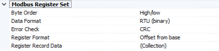
Byte Order
Default = High/Low. The byte order to use for encoding 'words' (two-byte sequences).
Data Format
Default = RTU (binary). The type of message transmission to use.
Error Check
Default = CRC. The type of message error checking to perform.
Register Format
Default = Offset from base. The register format to use.
Register Record Data
The register record configuration. Clicking the ... on the far right displays the Register Record Data collection editor discussed below.
Register Record Data Collection
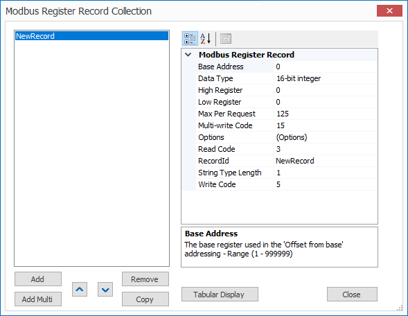
Click Add to enter the appropriate number of New Record items.
Click Remove to delete any unwanted New Record items.
Click Tabular Display to view all New Record items at once.
Saving Record Collection Changes
When record editing is complete, Click Close to return to the owning object type. Click the Save button .png?version=1&modificationDate=1557352230556&cacheVersion=1&api=v2) to save any changes made to the record collection.
to save any changes made to the record collection.
Base Address
Default = 0. The base register used in the 'Offset from base' addressing.
Data Type
Default = 16-bit integer. The data type to use for this register record.
High Register
Default = 0. The highest addressable register value in the range.
Low Register
Default = 0. The lowest addressable register value in the range.
Max Per Request
Default = 125. The maximum number of registers to request in one message for the register range.
Multi-write Code
Default = 15. The multi-write function code for the register range.
Options
- Read-only (Default = Selected).
- Perform single register writes (Default = Not selected).
- Always use multi-write function code (Default = Not selected).
- Subtract 1 from the register address (Default = Not selected).
- High/Low byte order (Default = Selected).
- High/Low word order (Default = Selected).
- High/Low dword order (Default = Selected).
Read Code
Default = 3. The read function code for the register range.
RecordId
The name of record in the collection.
String Type Length
Default = 1. The length of string type registers in this range.
Write Code
Default = 5. The write function code for the register range.
Related content
For assistance, please submit a ticket via our Support Portal, email autosol.support@autosoln.com or call 281.286.6017 to speak to a support team member.