Hex Repeater Template
- Michael Standal
- ken Halprin
- Emma Fullilove (Deactivated)
Overview
The Hex Repeater templates are xml files that define what commands can be sent to the device and what items are available for each command. It determines what the device will provide to ACM and OPC Clients.
Template Structure
The content of the template file consists of the following:
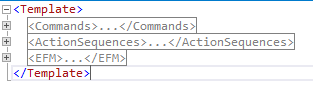
Template
An outer element named “Template” with three child elements:
- Commands – A container element to hold all of the commands supported by the device.
- ActionSequences – A container element to hold all of the action sequences defined for the device.
- EFM – A container element to hold all of the information that associates an item or log record column to an output location in a CFX (or other) output file. This element is discussed in the next section “Template Modification”.
Template Node Example
Commands
Each Hex Repeater command is defined in a “Command” element within the “Commands” element.
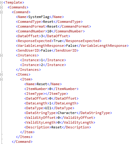
Command Node Example
Each “Command” element must have the following child elements:
- Name – The name of the command code
- CommandType – The command type, which indicates to ACM the type of logic performed. Valid command types are:
- Scan
- Reset
- Download
- Upload
- TimeDownload
- TimeUpload
- LogUpload
- LogPointerDownload
- CommandFormat – The command format, which defines the byte stream sent and received between ACM and the field device. Valid command formats are:
- Scan
- Reset
- Download
- Upload
- LogUpload
- TimeDownload
- TimeUpload
- CommandNumber – The command code number, in hexadecimal format, used by the command. Valid command code numbers can be an value between the range of 0x01 and 0xFE. Note, the CommandNumber format is in hexadecimal (all other numeric values in the template file are in decimal format) but must not include a leading ‘0x’. For example, the CommandNumber 0x3A would be respresented simply as: 3A.
- DataOffset – The location of the first byte of data in the response from the field device.
- ResponseExpected – A True/False value that determines if ACM should wait for a response from the device (this element should always have a True value).
- VariableLengthResponse – A True/False value that tells ACM if the response to the command can have varying length.
- SendUserID – A True/False value that indicates whether ACM should insert the configured User ID string into the transmitted message.
- Instances – A list of child elements that define the valid instance numbers for the command. Child elements are in the form:
<Instance>X</Instance>
Where ‘X’ is a number between 1 and 254.
- ManualInstances – (Optional) A list of instances that are available for a command but that do not provide data in a Scan poll. These are associated with manual log retrieval commands. Child elements are in the form:
<Instance>X</Instance>
Where ‘X’ is a number between 1 and 254.
- WritePair – A value that indicates another command number. Upload commands have a corresponding Download command that is their WritePair.
- ReadPair – A value that indicates another command number. Download commands have a corresponding Upload command that is their ReadPair.
- Items – A container element for the list of all items associated with the command.
Each Hex Repeater item is defined in an “Item” element within the “Items” element of the command it belongs to. Each “Item” element must have the following child elements:
- Name – The name of the item. The OPC item name for the item consists of the Command name, followed by a period ‘.’, and then followed by the item name.
- ItemNumber – An integer number assigned to the item. This value must be unique to all items with the same ItemType value.
- ItemType – An indicator of the type of data represented by the item. Valid values can be:
- ST – A discrete value (0 or 1) represented by a single bit in the response.
- EI – An analog value such as an integer or floating point number.
- AC – An accumulator. Typically an unsigned integer.
- DataOffset – The bit location in the data body section of the response that contains this item’s data. The data body location starts at the first byte after the return code.
- DataLength – The number of bits in the response that contain the item’s data.
- DataType – The data type for the item’s data value. Valid data types can be:
- I2 – Signed two-byte integer.
- I4 – Signed four-byte integer.
- R4 – Four byte (single precision) floating point number.
- Bool – Single bit.
- String – Variable length character data.
- UI1 – Unsigned one-byte integer.
- UI2 – Unsigned two-byte integer.
- UI4 – Unsigned four-byte integer.
- I1 – Signed one-byte integer (character).
- R8 – Eight byte (double precision) floating point number.
- Julian – Four byte integer representing a Julian date value.
- DataStringType – The expected type or format of the data for items that have a DataType of ‘String’. Valid types can be:
- Character String – Variable length string.
- Character – Single character string.
- Ascii Character – Two character string with character order reversed.
- ValidityOffset – The offset (or zero if not used) of a bit in the response that indicates whether the items data is valid, or usable. This applies only to Scan command items.
- ValidityLength – The length, in bits, of the validity bit(s) located at the ValidityOffset. This value should always be 1.
- Description – A free-form description for the item.
ActionSequences
Each Hex Repeater action sequence is defined in an “ActionSequence” element within the “ActionSequences” element.
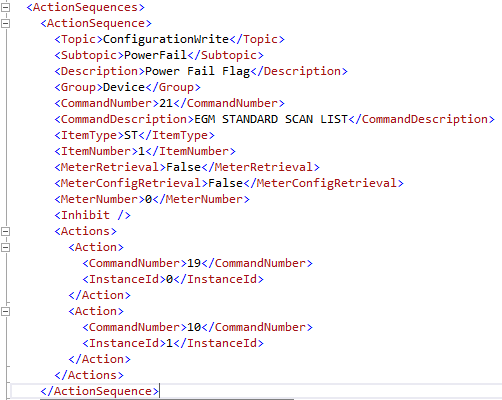
ActionSequence Node Example
Each “ActionSequence” element must have the following child elements:
- Topic – Text that describes the high-level type of action. Supported options include:
- ConfigurationRead
- ConfigurationWrite
- LogRead
- Subtopic – Text that identifies a lower-level area affected by the action. This text typically includes a meter number or instance number (if applicable) appended to the text and preceded by an underscore. Examples include:
- EGMDataChange_1
- EGMDataChange_2
- AnalogDataChange_1
- AnalogDataChange_4
There are two reserved words that are used for an action sequence that requires a full configuration of the field device. The text “PowerFail” and “LostAllData” are specifically detected by the ACM Hex Repeater driver to handle special case configuration actions.
- Description – Free-form text to describe the action sequence.
- CommandNumber – The command number whose response can trigger the action sequence (see the description below that describes how an action sequence is triggered).
- CommandDescription – Free-form description of the command.
- ItemNumber – The item number of the item that can trigger the action sequence (see the description below that describes how an action sequence is triggered).
- MeterRetrieval – A True/False value indicating whether this action sequence is meter related.
- MeterConfigRetrieval – A True/False value indicating whether this action sequence is related data that contains meter configuration/characteristics.
- MeterConfigRetrieval – A True/False value indicating whether this action sequence is related data that contains meter configuration/characteristics.
- MeterNumber – The one-based meter run number (used only if the “MeterRetrieval” element has a True value, or if the “MeterConfigRetrieval” element has a True value).
- Inhibit – Indicates an item that can inhibit the action sequence from running if its value is True. The “Inhibit” element can be empty, but if not empty it requires three child elements:
- CommandNumber – The command number of the inhibiting item.
- ItemType – The item type of the inhibiting item (must be one of the acceptable item type identifiers used in the “Item” element).
- ItemNumber – The item number of the inhibiting item.
- Actions – A list of actions to be executed if the action sequence is triggered. Actions are executed in the order in which they’re listed in the template. If any action fails, the remaining actions are discarded. The “Actions” element contains a variable length list of “Action” elements. Each “Action” element contains these child elements:
- CommandNumber – The command number identifies the Hex Repeater message to send to the device.
- InstanceId – The instance identifier to send with the command message.
An action sequence is triggered when all of the following criteria are met:
- A Scan command response has an ‘On’ (or True, or ‘1’) value for the item associated with the action sequence. That is, an item in a Scan command identified by its CommandNumber, ItemNumber, and ItemType has an ‘On’ value, and that item’s CommandNumber, ItemNumber and ItemType are specified in an action sequence.
- A Scan command response has an ‘Off’ (or False, or ‘0’) value for the item (if any) associated with the action sequence inhibit.
- The action sequence must belong to a subtopic that is enabled through the Action Sequence Group Enable property in the ACM Hex Repeater configuration.
EFM
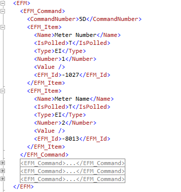
EFM Node Example
The EFM node is used to tell the protocol driver how to assign data for a CFX file (or PGAS file) from the items that are retrieved with a given command.
Template Modification
The “EFM” element is the only one that may need manual modification.
In this template example, command 5D is used to read a single item -- the name of the meter. The xml for that command definition is listed below:
<Command>
	<Name>EGMMeterInfo_Read</Name>
	<CommandType>Upload</CommandType>
	<CommandFormat>Upload</CommandFormat>
	<CommandNumber>5D</CommandNumber>
	<DataOffset>3</DataOffset>
	<ByteCount>12</ByteCount>
	<ResponseExpected>True</ResponseExpected>
	<VariableLengthResponse>False</VariableLengthResponse>
	<SendUserID>False</SendUserID>
	<SendByteCount>True</SendByteCount>
	<ResponseOptions>7</ResponseOptions>
	<WritePair>5E</WritePair>
	<Instances>
		<Instance>1</Instance>
		<Instance>2</Instance>
		<Instance>3</Instance>
		</Instances>
			<Items>
				<Item>
					<Name>Value1</Name>
					<ItemNumber>1</ItemNumber>
					<ItemType>EI</ItemType>
					<DataOffset>0</DataOffset>
					<DataLength>96</DataLength>
					<DataType>String</DataType>
					<DataStringType/>
					<ValidityOffset>0</ValidityOffset>
					<ValidityLength>0</ValidityLength>
					<Description>Meter Id</Description>
				</Item>
			</Items>
</Command>
The “Items” element has one “Item” element that defines the value for the single item in this command. In this example, the item’s number is ‘1’ (defined in the “ItemNumber” element) and its type is “EI” (defined in the “ItemType” element). The item’s description is ‘Meter Id’.
To direct that item to the correct location in a CFX file (or PGAS file), an entry is added to the “EFM” element for that command and item; including the item’s number and type:
<EFM>
	<EFM_Command>
		<CommandNumber>5D</CommandNumber>
			<EFM_Item>
				<Name>Meter Number</Name>
				<IsPolled>T</IsPolled>
				<Type>EI</Type>
				<Number>1</Number>
				<Value></Value>
				<EFM_Id>-1027</EFM_Id>
			</EFM_Item>
	</EFM_Command>
</EFM >
An “EFM_Command” element is added with one “EFM_Item” element (more than one “EFM_Item” element can exist within the “EFM_Command” element if more than one item is associated with the command and more than one item has to be identified for CFX (or PGAS)).
The “EFM_Command” element must specify the Hex Repeater command that retrieves the item’s value. Each item that must be identified in an “EFM_Item” element must have the following nodes:
- Name – A descriptive name for the item.
- IsPolled – A ‘T’rue or ‘F’alse to indicate whether this item’s data comes from polling the Hex Repeater device or whether it is a fixed value that resides in the xml file itself. If an item is polled from the device, but a fixed value should be used instead then three changes must be made to the “EFM_Item” element. 1) Set “IsPolled” to False; 2) Add the desired value to the “Value” element; 3) Set the “Number” element to a value that is unique within the command’s items and greater the last polled item number. These settings will add a new item to the output record with the desired EFM mapping identifier. The polled item will still be in the output record as well, but it will not be assigned any EFM identifier.
- Type – A type identifier. If the item is polled, the type and number must match the type and number of one of the items in the “Command” element.
- Number – An item number. If the item is polled, the type and number must match the type and number of one of the items in the “Command” element.
- Value – The value to be used for the item if it is not polled.
- EFM_Id – The ACM identifier that represents the meaning of the item (in this example, -1027 is the identifier for Meter Id).
One other format for the “EFM_Item” element is acceptable and used for the case where a value read from the device must be translated into a meaningful value for CFX (or PGAS). In this format, the “Value” element is expanded to include translation information:
<Value>
	<MappedValue>
		<Value>U</Value>
		<EFM_ID>-4037</EFM_ID>
	</MappedValue>
	<MappedValue>
		<Value>D</Value>
		<EFM_ID>-4036</EFM_ID>
	</MappedValue>
</Value>
When value translation is required, the “Value” element must have a “MappedValue” element for each possible value that is read from the device. The “MappedValue” element has these children:
- Value – A value for the item that is read from the device. The example above shows that the letters ‘U’ or ‘D’ can be provided by the device.
- EFM_ID – The ACM identifier that represents the meaning of the item’s value. In the example above, -4037 (ACM’s identifier for Upstream) is used for the value ‘U’; and -4036 (ACM’s identifier for Downstream) is used for the value ‘D’.
Data Files
Upload Command Data
Whenever an ‘Upload’ command is sent, the driver retrieves the data and updates any OPC items that may be advised. The driver also stores the data in a file.
Those files are typically located here: C:\ProgramData\Autosol\Communication Manager\7\DataFiles\HexRepeater\UploadCommandData
The data is stored in files with names created from the ACM object id number, the command number, and the instance number. The command number is actually the ‘Download’ command number that goes along with the ‘Upload’ command number that was used to retrieve the data (Upload and Download commands come in pairs).
A typical file name will look like this: Device_00005_Command_4A_Instance_01.txt
The files are stored because the device is able to tell the driver that it has lost its configuration. When the device signals that is has lost its configuration, the driver reads those files and sends ‘Download’ commands with the data previously retrieved and stored. That data restores the device’s configuration.
You may occasionally see an error log message that says, “Failed to open upload storage data file “<filename>””. This doesn’t always indicate an error situation. The message may appear in the log for any of these reasons:
- ACM has just sent an upload command to read data and is now trying to store the information for later use. If ACM can’t create or open the file, it will log this error. This should only happen if ACM doesn’t have permission to create the file in its ‘data files’ path or can’t create the path where it needs to store the file.
- ACM has received an OPC write to an item that belongs to an upload/download command pair. To write the item, ACM must write the entire data content of the download command. The data content is what’s read from the device during an upload command and stored in the upload file. Any of these three conditions might occur when ACM receives an OPC write for one or more download items:
- ACM can successfully find and read the upload data file. It will write the full data content in the download command along with any OPC write item data, and the above error will not be logged.
- The upload file doesn’t exist. ACM may not have performed an upload for the specific command, or the file may have been manually deleted or moved. If the file doesn’t exist, the above error message will be logged. When this happens, ACM performs an upload command before issuing the write command. After the upload command has completed, ACM stores the upload data from the command in the data file. It then uses the upload data, plus any values it received during the OPC write, and sends a download command with the new data. If that completes successfully, ACM will store the upload data including the new written value(s) in the upload storage file.
- ACM performs an upload command and tries to store the data content from the command. If it cannot create the file for the data storage, it will log the above error message. If this happens, the probable cause is that ACM does not have permission to create the file or one of the directories in the file storage path.
Event Data
Change Event Data Item Mapping
The following table shows the mapping between the item text parsed (EFM_Item.Name) from the device to the EFM_Item.EFM_ID for publishing.
Note
Some Item entries are duplicated indicating more than one mapping exists for an item due to the string name differing by template load.
| Item Name | EFM ID |
|---|---|
| Nitrogen - Mole % | -2012 |
| Methane - Mole % | -2011 |
| CO2 - Mole % | -2003 |
| Ethane - Mole % | -2004 |
| Propane - Mole % | -2022 |
| i-butane - Mole % | -2009 |
| n-butane - Mole % | -2013 |
| i-pentane - Mole % | -2010 |
| n-pentane - Mole % | -2020 |
| n-hexane - Mole % | -2017 |
| n-heptane - Mole % | -2016 |
| n-octane - Mole % | -2019 |
| n-nonane - Mole % | -2018 |
| n-decane - Mole % | -2014 |
| H2S - Mole % | -2007 |
| H2O - Mole % | -2006 |
| Helium - Mole % | -2008 |
| oxygen - Mole % | -2021 |
| CO - Mole % | -2002 |
| Hydrogen - Mole % | -2005 |
| Argon - Mole % | -2001 |
| Specific Gravity | -1040 |
| Temp when Line measu | -1035 |
| Temp when Orif measu | -1032 |
| Orifice Size | -1030 |
| Line Size | -1033 |
| Orifice Type | -1031 (See Mapped Values Table Below) |
| Line Type | -1034 (See Mapped Values Table Below) |
| Pipe Taps Location | -1045 (See Mapped Values Table Below) |
| Atmos. Pres. | -1001 |
| Contract Pres. Base | -1002 |
| Contract Temp. Base | -1003 |
| Low DP Limit - No Fl | -1014 |
| ATMOS-PR | -1001 |
| ORI-SIZE | -1030 |
| LINE-SIZE | -1033 |
| FT-OF-LINE-MEAS | -1035 |
| FT-ORI-BORE-MEAS | -1032 |
| TAP-LOCATION(0-or-1) | -1045 (See Mapped Values Table Below) |
| ORI-PLAT-TYP(0-1-or- | -1031 (See Mapped Values Table Below) |
| LINE-TYP(0-1-or-2) | -1034 (See Mapped Values Table Below) |
| Low-DP-Cutoff | -1015 |
| FCALC-SELECT | -7002 (Unknown Value) |
| DYNAMIC-VISCOSITY | -1053 |
| HV-Man-Val | -6057 |
| SG-Man-Val | -1040 |
| CO2--CARB-DIOXIDE | -2003 |
| N2-----NITROGEN | -2012 |
| C1-----METHANE | -2011 |
| C2-----ETHANE | -2004 |
| C3-----PROPANE | -2022 |
| H2O----WATER | -2006 |
| H2S----HYD-SULFIDE | -2007 |
| H2-----HYD | -2005 |
| CO----CARB-MONOXIDE | -2002 |
| O2-----OXYGEN | -2021 |
| IC4----I-BUTANE | -2009 |
| NC4--N-BUTANE | -2013 |
| IC5----I-PENTANE | -2010 |
| NC5--N-PENTANE | -2020 |
| C6-----HEXANE | -2017 |
| C7-----N-HEPTANE | -2016 |
| C8-----N-OCTANE | -2019 |
| C9-----N-NONANE | -2018 |
| C10---N-DECANE | -2014 |
| He-----HELIUM | -2008 |
| Ar-----ARGON | -2001 |
| CONTRACT-BASE-PR | -1002 |
| CONTRACT-BASE-FT | -1003 |
| CONTRACT-HOUR | -1009 |
| Dry ideal BTU | 0 |
| Pres. Index | 0 |
| Temp. Index | 0 |
| Low DP Index | 0 |
| High DP Index | 0 |
| Volume Index | 0 |
| Flow Index | 0 |
| Calib. Switch Index | 0 |
| Maint. Switch Index | 0 |
| Turbine Meter Index | 0 |
| Meter ID Number | 0 |
| User Description | 0 |
| Temp. Units | 0 |
| Orifice / Turbine | -1029 (See Mapped Values Table Below) |
| Pres. Conversion Fac | 0 |
| DP Conversion Fac | 0 |
| Flow Conversion Fac | 0 |
| Line Sz Conversion F | 0 |
| Orifice Sz Conver. F | 0 |
| Turbine Meter Factor | 0 |
| Low Turbine Meter Lm | 0 |
| High Turbine Meter L | 0 |
| Volume Corr. Factor | 0 |
| Volume Conversion Fa | 0 |
| FPV Analysis Method | -1021 (See Mapped Values Table Below) |
| Temp. Manual / Instr | 0 |
Change Event Data Item Mapped Values
The following table shows the mapped values used when an item's value is mapped to an EFM ID based on a value passed.
| Item Name | Value | EFM ID |
|---|---|---|
| Pipe Taps Location | U | -4037 |
| Pipe Taps Location | D | -4036 |
| Orifice Type | Stainless | -4023 |
| Orifice Type | Carbon Steel | -4021 |
| Orifice Type | Monel | -4022 |
| Line Type | Stainless | -4023 |
| Line Type | Carbon Steel | -4021 |
| Line Type | Monel | -4022 |
| TAP-LOCATION(0-or-1) | U | -4037 |
| TAP-LOCATION(0-or-1) | D | -4036 |
| ORI-PLAT-TYP(0-1-or- | Stainless | -4023 |
| ORI-PLAT-TYP(0-1-or- | Carbon Steel | -4021 |
| ORI-PLAT-TYP(0-1-or- | Monel | -4022 |
| LINE-TYP(0-1-or-2) | Stainless | -4023 |
| LINE-TYP(0-1-or-2) | Carbon Steel | -4021 |
| LINE-TYP(0-1-or-2) | Monel | -4022 |
| Orifice / Turbine | O | -4028 |
| Orifice / Turbine | T | -4030 |
| Orifice / Turbine | V | -4032 |
| FPV Analysis Method | D | -4017 |
| FPV Analysis Method | G | -4018 |
Related content
For assistance, please submit a ticket via our Support Portal, email autosol.support@autosoln.com or call 281.286.6017 to speak to a support team member.