DF1 Configuration
See the Common Device Configuration guide for assistance configuring the General, Options, Details, and Logging tabs. See the Connection/Schedule page for assistance with the Connection tab.
Device Tab
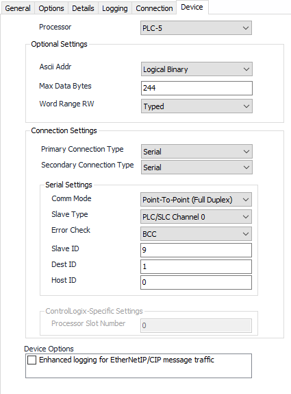
Processor
Default = PLC-5. Select the processor type in use for this configuration.
Ascii Addr
- Logical Binary (Default).
- Logical ASCII.
Max Data Bytes
Default = 244. Used to control the maximum number of data bytes requested by the PLC. This will be capped by the value entered here, or by the maximum supported by the selected Processor, whichever is lower.
Word Range RW
Word Range Read Write
- Typed (Default).
- Word Range.
Note
Primary and Secondary Communication Type refers to the final physical connection to the device (Ethernet or Serial). As such, the Serial Settings section only applies if either the Primary or Secondary connection type is set to serial. Otherwise, the Serial Settings section is disabled.
Primary Connection Type
Default = Serial. Select Serial or Ethernet.
Secondary Connection Type
Default = Serial. Select Serial or Ethernet.
Comm Mode
- Master (Half Duplex).
- Point-To-Point (Full Duplex) (Default).
- Peer-To-Peer (Full Duplex).
Slave Type
- PLC/SLC Channel 0. (Default).
- Data Highway Module.
Error Check
- BCC. (Default).
- CRC.
Slave ID
Default = 9.
Dest ID
Default = 1.
Host ID
Default = 0.
ControlLogix®-Specific Settings
The ControlLogix®-Specific Settings are enabled only if ControlLogix® is selected as the processor type. The Processor Slot Number refers to the physical slot in the chassis where the processor resides. This number is zero-based with zero being the default.
Device Options
The Enhanced Logging option at the bottom outputs additional debug information about each message sent which may be helpful in a support situation.
For assistance, please submit a ticket via our Support Portal, email autosol.support@autosoln.com or call 281.286.6017 to speak to a support team member.